Electric Heating Device

Pending Publication Date: 2021-02-04
EBERSPACHER CATEM
View PDF16 Cites 2 Cited by
  • Summary
  • Abstract
  • Description
  • Claims
  • Application Information

AI Technical Summary

Benefits of technology

[0022]Once the layers of the layer structure have been braced in the receiving pocket by the pressure element, the mass is filled into the pocket. This mass may fill all the free spaces in the pocket so that good heat transfer from the PTC element to all inner surfaces of the pocket arises, including the end faces thereof. The mechanical bracing is maintained by the spring segments of the pressure element. T

Problems solved by technology

However, there is the problem that the receiving pocket does not always correspond to the designed shape due to manufacturing tolerances.
For production reasons, the PTC elements are subject to considerable dimensional fluctuations.
It is also not always ensured that the heat extraction surfaces of the PTC element run completely straight and planar.
Pressing in a wedge as a pressure element can lead to stress peaks, due to which the PTC element or a ceramic insulating layer can break inside the receiving pocket.
Depending on the tolerances, the wedge element used as a pressure element in prior art in the specific applica

Method used


Image

  • Electric Heating Device
  • Electric Heating Device
  • Electric Heating Device

Examples


Example

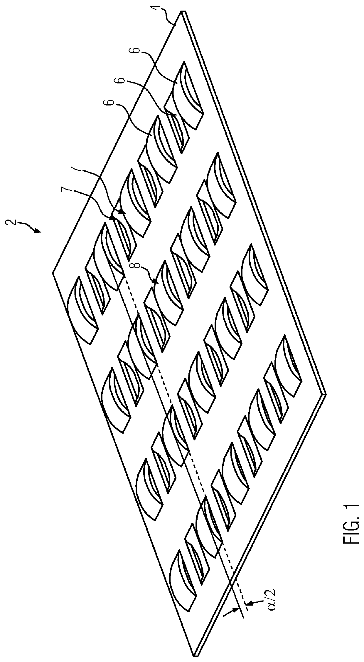
[0030]FIG. 1 shows an embodiment of a pressure element 2 according to the invention comprising a sheet metal strip identified with reference number 4 from which spring segments 6 are worked out by punching and bending. The spring segments 6 are formed by punching out lateral edges 7 and bending tabs 8 resulting therefrom. The tabs 8 are each connected with one of their two end sides to the base material of the sheet metal strip 4. This results in spring segments 2 having a relatively high spring rigidity.

[0031]It can be seen that each first spring segment 6 of a row with parallel spring segments 2 is bent out toward the one side and each second spring segment 6 to the other side of the sheet metal strip 4

[0032]A straight line can be applied at the respective outer surface points of the individual spring segments 6. The straight lines disposed opposite one another and connecting the metal strips 4, of which only straight line I on the face side is fully shown in FIG. 1 and the other ...


PUM


Abstract

An electric heating device includes a housing having a partition wall which separates a connection chamber from a heating chamber for dissipating heat and from which at least one receiving pocket, protruding into the heating chamber as a heating rib tapering towards its lower, closed end protrudes. A PTC heating element includes at least one PTC element and conductor tracks for energizing the PTC element with different polarities. The conductor tracks are electrically conductively connected to the PTC element and are electrically connected in the connection chamber. A pressure element is received which holds heat extraction surfaces of the PTC element abutted against oppositely disposed inner surfaces of the receiving pocket. The pressure element includes a sheet metal strip which, by punching and bending, forms spring segments protruding from the plane of the sheet metal strip. The spring elements are provided in a planar manner distributed over a heat extraction surface of the PTC element provided adjoining the respective pressure element.

Description

BACKGROUND OF THE INVENTION1. Field of the Invention[0001]The present invention relates to an electric heating device with a housing having a partition wall which separates a connection chamber from a heating chamber for dissipating heat. At least one receiving pocket protruding into the heating chamber as a heating rib protrudes from the partition wall. A PTC heating element is provided in this pocket. Furthermore, a pressure element is accommodated in the pocket and holds heat extraction surfaces of the PTC element abutted against opposite inner surfaces of the receiving pocket.2. Background of the Invention[0002]The PTC heating element has at least one PTC element and conductor tracks abutting thereagainst in an electrically conductive manner. The conductor tracks are connected to the PTC element in an electrically conductively manner. This connection can be a positive-fit and / or force-fit and / or positive substance-fit connection.[0003]The aforementioned general features of the e...

Claims


Application Information

Patent Timeline
IPC IPC(8): H05B3/50
CPCH05B3/50H05B2203/023H05B2203/02H05B3/10H05B3/02H05B3/06F24H9/1827F24H2250/04B60H2001/2271B60H1/2221F24H1/102F24H1/10F24H1/121H05B2203/021
Inventor WALZ, KURTNIEDERER, MICHAELKACHELHOFFER, PATRICK
Owner EBERSPACHER CATEM
Why Eureka
Try Eureka