Filter for a filtration device

Active Publication Date: 2021-02-11
ABP AQUILINA BOUVIER POOL
View PDF306 Cites 1 Cited by
  • Summary
  • Abstract
  • Description
  • Claims
  • Application Information

AI Technical Summary

Benefits of technology

The present patent is about a filter for use in a water filtration system. The filter has an annular upper end, a bottom wall, and a side wall. The side wall and bottom wall have orifices to allow water to flow through while retaining solid elements. The filter is designed to be inserted into an inlet duct of the filtration system with the longitudinal axis of the filter parallel to the inlet axis. The filter can be adjusted in size by adjusting the inclination of its arms. The filter can be inserted into the inlet duct with the longitudinal axis parallel to the inlet axis and then released, allowing the arms to move away from the longitudinal axis and come to rest against the inlet duct. The technical effect of this design is that the filter can be easily inserted into the filtration system and can adapt to different inlet diameters.

Problems solved by technology

The total number of inlet filter models is nowadays high, which makes it difficult to replace filters on older models.
Indeed, the professional sellers of swimming pool equipment cannot have all the references suitable for the different skimmer models.
This leads to long lead times and high replacement costs.
Without an inlet filter, these elements penetrate into the skimmer, hindering its operation.

Method used


Image

  • Filter for a filtration device
  • Filter for a filtration device
  • Filter for a filtration device

Examples


first embodiment

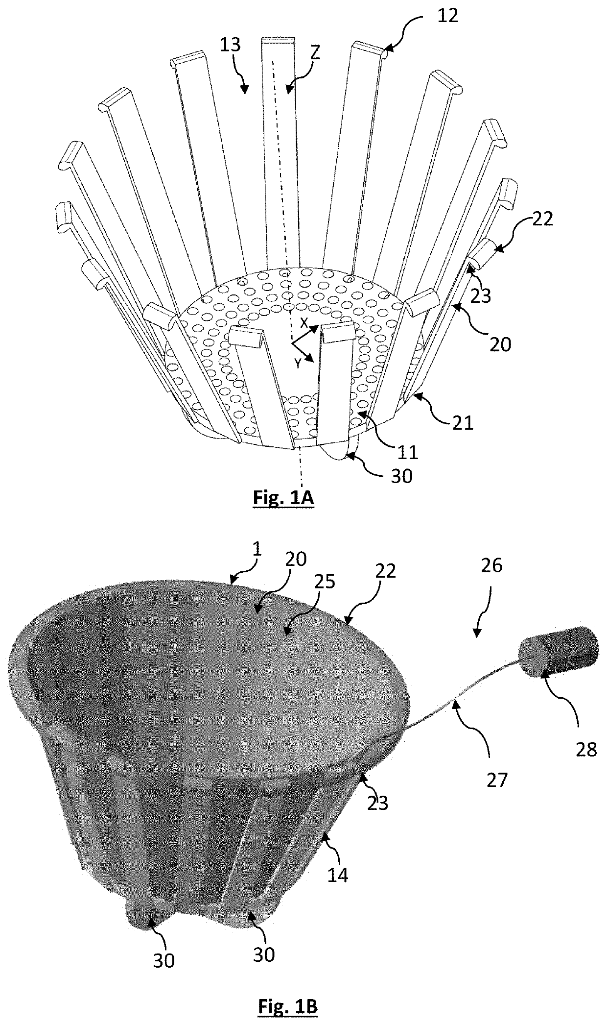
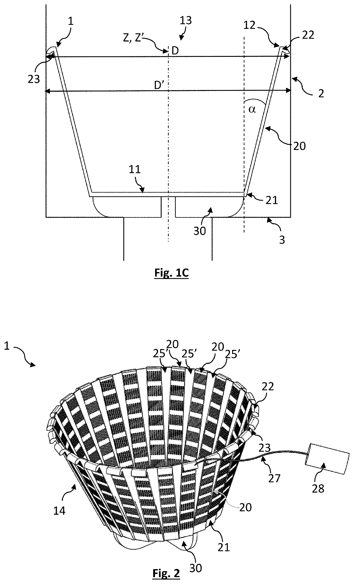
[0036]a filter 1 according to the present disclosure is shown in FIGS. 1A to 1C. It is intended to be introduced into an inlet duct 2 of a filtration module or skimmer. According to this embodiment, the filter 1 comprises a body represented in FIG. 1A. The body of the filter 1 has a bottom wall 11, forming a filter bottom. The bottom wall 11 extends around a longitudinal axis Z.

[0037]In this example, the bottom wall 11 extends in a radial plane XY, perpendicular to the longitudinal axis Z. The bottom wall 11 is preferably parallel or substantially parallel to the radial plane XY. Substantially parallel means parallel within an angular tolerance of + / −30°. Preferably the bottom wall 11 is symmetrical with respect to the longitudinal axis Z. The bottom wall 11 may be solid or have orifices, the latter being intended to collect solid elements that it is desired to retain in the filter 1. The solid elements may be, in particular, plants, insects, stones or other solid elements that are ...

third embodiment

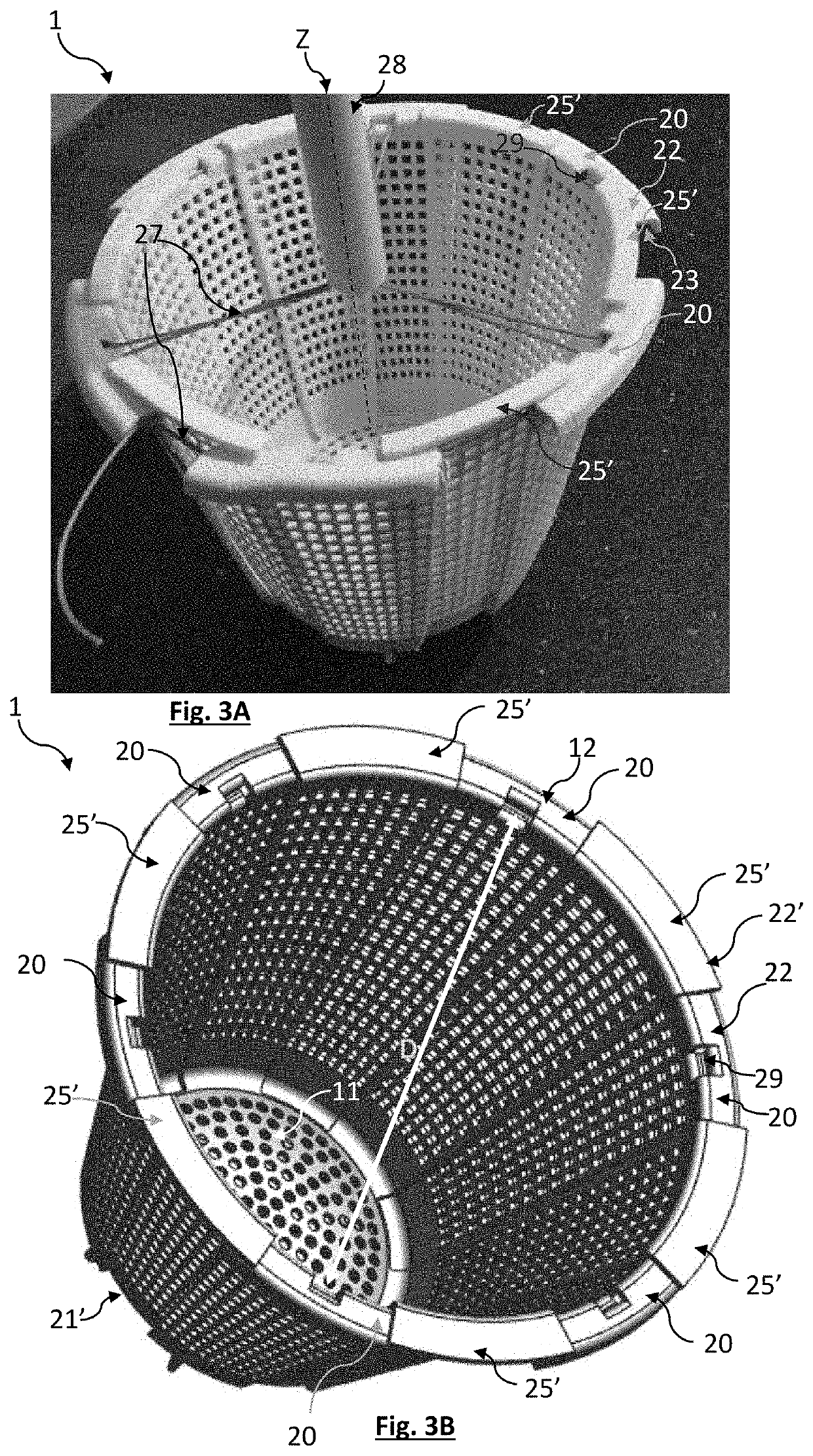
[0057]FIGS. 3A to 3C represent the present disclosure, according to which the filter 1 has a side wall (the side wall 14) formed by rigid arms 20. As previously described, the arms 20 extend between the lower edge 21, connected to the bottom wall 11, and the upper edge 22. The side wall 14 is also formed by the complementary wall 25, the latter comprising elementary sections 25′ separated from each other. Each elementary section 25′ extends between two adjacent arms 20. Each elementary section 25′ is connected to the bottom wall 11, and has an upper edge 22′, capable of moving away from or towards the longitudinal axis Z.

[0058]In this third embodiment, the arms 20 and the elementary sections 25′ are rigid. As can be seen in FIG. 3A, each elementary section 25′ is partially superimposed on the two adjacent arms 20 to which it is connected. The portion of the elemental section superimposed on an arm (of arms 20) varies depending on the distance of the arm 20 from the longitudinal axis...


PUM

PropertyMeasurementUnit
Angleaaaaaaaaaa
Flow rateaaaaaaaaaa
Diameteraaaaaaaaaa

Abstract

A filter, for insertion into an inlet duct of a water filtration system, has an annular upper end delimiting an opening around a longitudinal axis and defining a filter diameter. A side wall extends, around the longitudinal axis, between the annular upper end and a bottom wall that extends opposite the opening. The side and / or bottom walls have orifices to allow water to flow therethrough while retaining solid elements. The sidewall wall comprises a plurality of arms that each extend between a lower edge, connected to the bottom wall, and an upper edge forming part of the annular upper end. Each arm extends along an adjustable inclination so that the filter diameter is variable according to the inclination of each arm. When the filter is inserted into the inlet duct, the inclination of the arms is adjusted so that the filter diameter is adapted to the inlet diameter.

Description

CROSS-REFERENCE TO RELATED APPLICATIONS[0001]This application is a national phase entry under 35 U.S.C. § 371 of International Patent Application PCT / FR2018 / 053146, filed Dec. 6, 2018, designating the United States of America and published as International Patent Publication WO 2019 / 150006 A1 on Aug. 8, 2019, which claims the benefit under Article 8 of the Patent Cooperation Treaty to French Patent Application Serial No. 1870118, filed Feb. 2, 2018.TECHNICAL FIELD[0002]The present disclosure relates to a filter intended to be disposed in a water filtration device, for example in a swimming pool skimmer.BACKGROUND[0003]Filtration devices for pool skimmers generally have a first filtration stage with an inlet filter acting as a pre-filter. Currently each skimmer model has its own inlet filter model. Each skimmer manufacturer has several different skimmer models. Skimmers have an inlet duct, the geometry of which varies according to the model, especially the diameter and height. The to...

Claims


Application Information

Patent Timeline
IPC IPC(8): B01D29/23E04H4/12
CPCB01D29/23B01D2201/31B01D2201/02E04H4/1272C02F2103/42
Inventor AQUILINA, YANNBOUVIER, MATTHIEU
Owner ABP AQUILINA BOUVIER POOL
Why Eureka
Try Eureka