Miter clamping system

Active Publication Date: 2021-02-11
STOUFFER RODNEY SCOTT
View PDF4 Cites 1 Cited by
  • Summary
  • Abstract
  • Description
  • Claims
  • Application Information

AI Technical Summary

Benefits of technology

[0017]The clamping system combines powerful unique features into a small efficient, safe and easy to use package. It offers diverse industries a reliable, precision method of securing smooth flat materials of all kinds to be installed or bonded together. The soft, ribbed “no footprint” lip seals of the vacuum base plate are preferably the only part of the damping system to touch the subject material. Handles allow for carrying and positioning large, or small, pieces to redu

Problems solved by technology

The mitered edges are easily chipped or broken.
Many shops refrain from offering the mitered edge detail due to the manpower required and the catastrophic losses that can occur from the fabricators inability to re-align and securely clamp these seams before the rapid curing epoxy adhesive sets.
The shortcomings of this system, include: 1) an additional apparatus required to compensate for the “outswing” of waterfall or mitered apron seams caused by its own normal operation; 2) added complexity of multiple additional suction cup attachments required to resist the inherent, unnoticeable “side slipping” ease of the suction cups potentially resulting in a failed seam, consequent loss of materials, labor, install deadlines, personal injury and collateral damage when the assumed secure stone section slams down; and 3) the inability to accommodate seam angles other than perpendicular ninety degrees.
Other clamping devices have various limitations such as rigid vacuum pads limited by 1) inability to clamp a mitered apron or waterfall larger than ten inches, 2) perpendicular operation, 3) uni

Method used


Image

  • Miter clamping system
  • Miter clamping system
  • Miter clamping system

Examples


Embodiment Construction

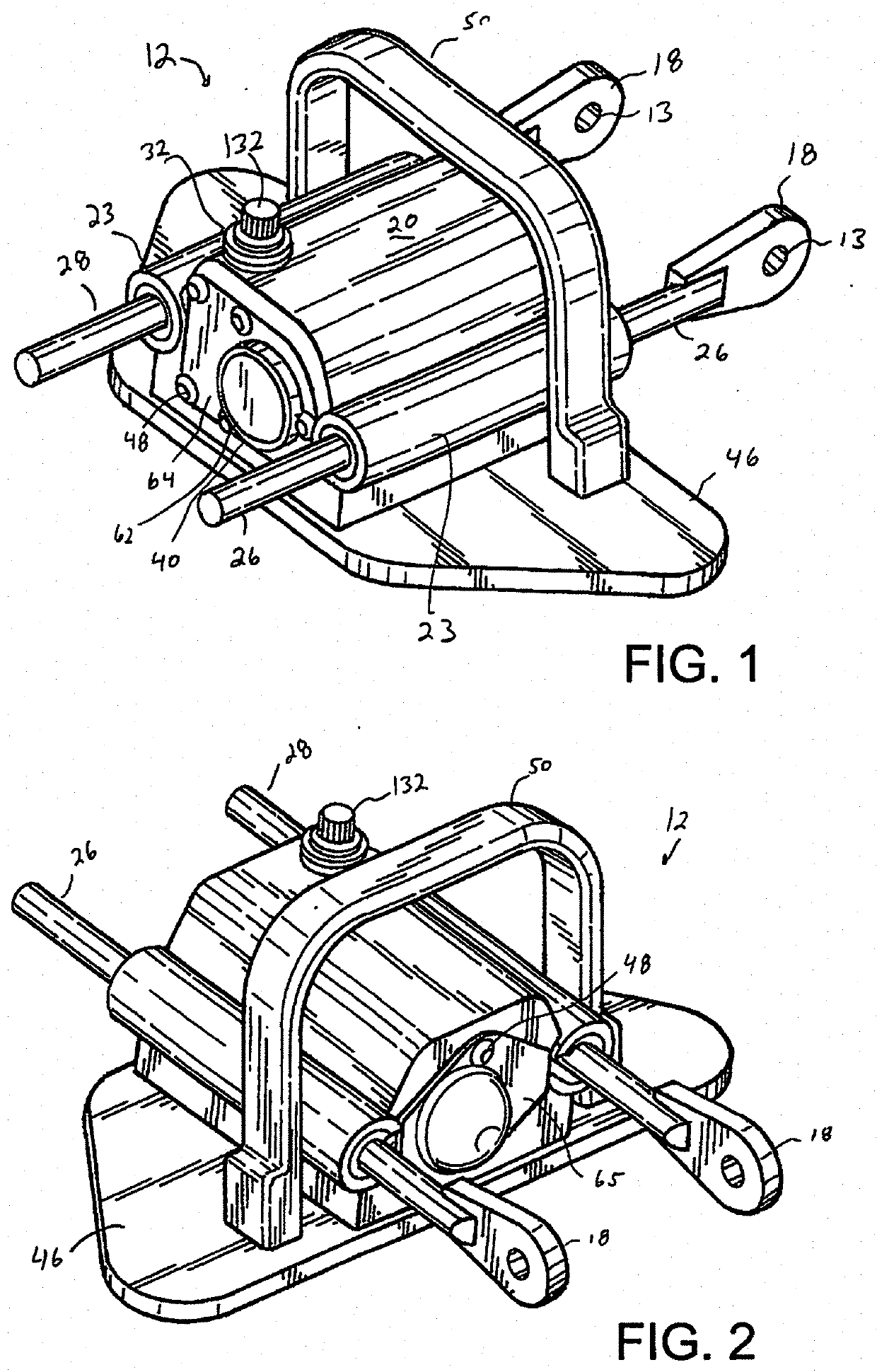
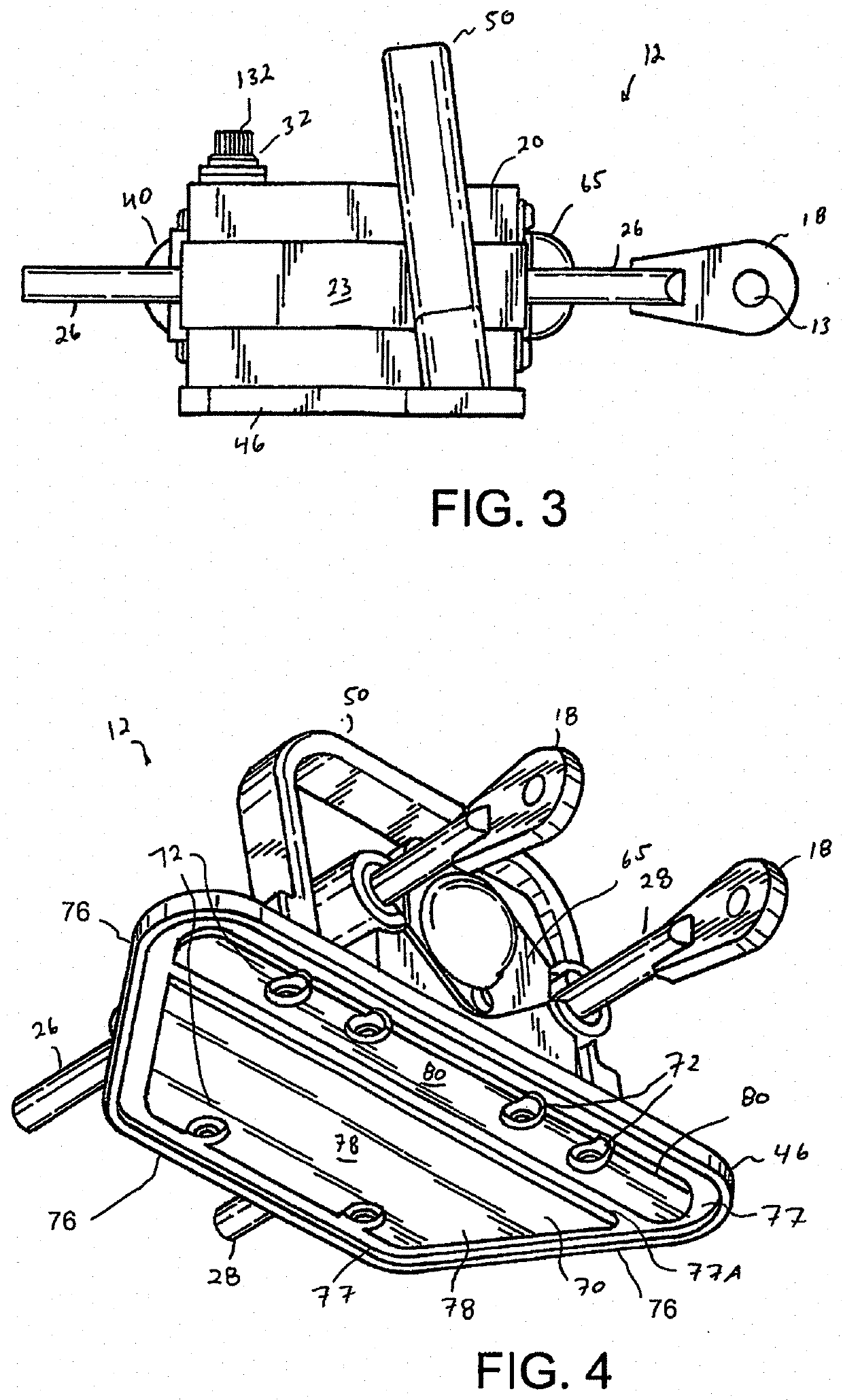
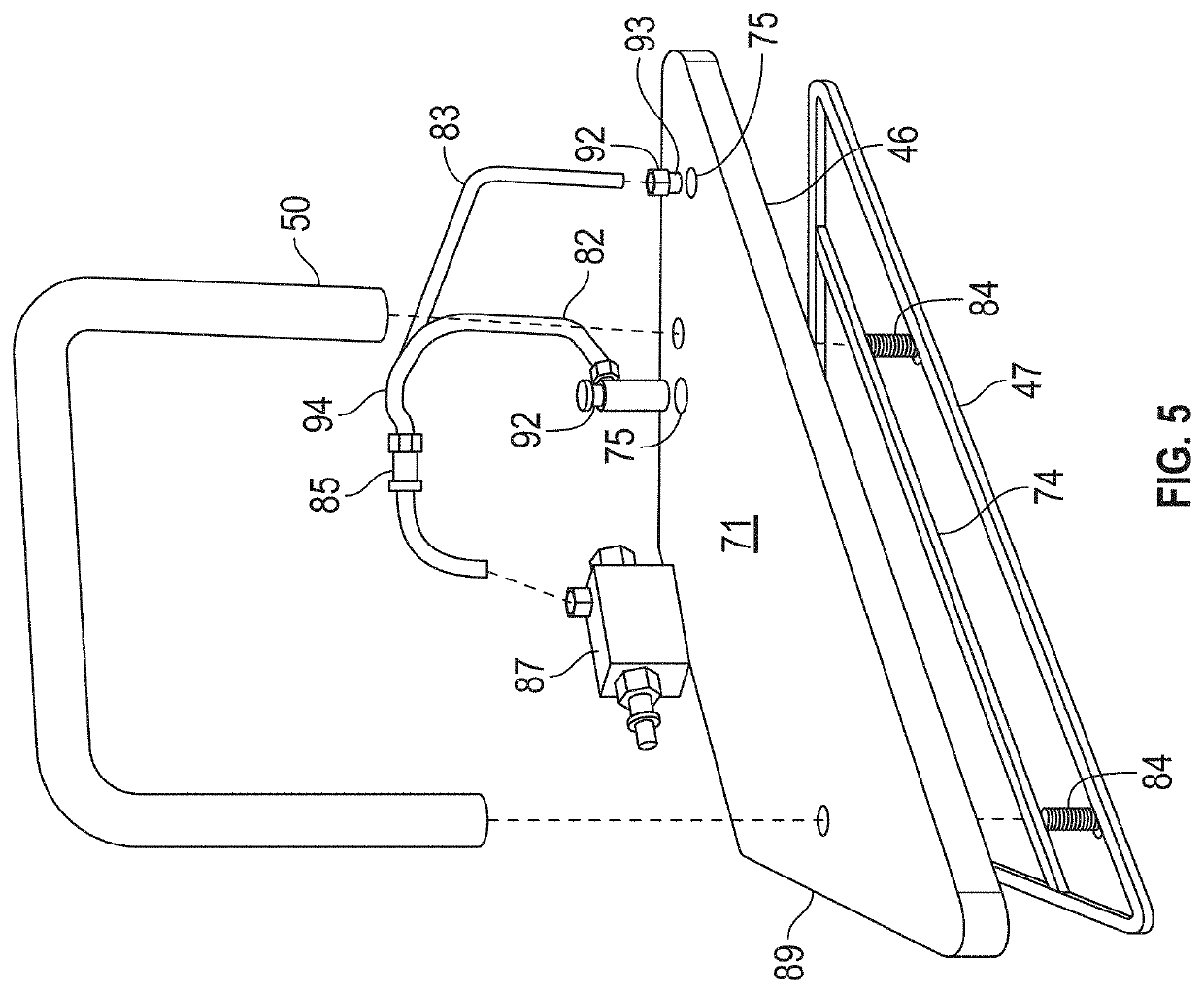
[0053]The clamping system of the present invention has diverse industrial potential for use with materials such as stone, solid surface, wood, glass, metal, tile and more (generally referred to as slabs). The clamping system of the present invention firmly secures to the subject material with a near “zero footprint” rigid vacuum plate (as opposed to standard suction cups, etc.) to allow for the simultaneous precision dry fit of mitered pieces. Fit pieces can be expanded, or moved, apart without damage or misalignment for cleaning and gluing. In production of corners, the system can secure all three mitered pieces of a corner finished end detail. The knuckles may adjust to any desired angle between forty five and two hundred seventy degrees as between the units and / or vacuum plates. The system may be equipped with a handle bar on each unit for safe easy material handling by only one worker. The system may secure mitered edge pieces as small as one-and-one-half inches tall, and as lar...


PUM


Abstract

A clamping system useful in miter edge fabrication. Two separate units, each including a vacuum plate may be placed on'separate slabs. The units are connected with a knuckle that can be rotated to provide connection of the slabs in a variety of angles. The units are vacuum sealed to the slabs via pressure tubes. The vacuum plates may include various sections of varied sizes to connect to different sized slabs. When the knuckle is locked, a worm gear will provide for lateral movement, relative the knuckle, to provide precision fitting of slabs.

Description

CLAIM OF PRIORITY[0001]The present continuation-in-part application includes subject matter disclosed in and claims priority to PCT patent application PCT / US18 / 65503 filed Dec. 13, 2018, entitled “Miter Clamping System” and incorporated herein by reference, and also provisional patent application entitled “Method for Positioning Perpendicular, Planar Materials by Means of a Portable Pneumatic Mitre Clamp Apparatus” filed Dec. 13, 2017 and assigned Ser. No. 62 / 708,556, both incorporated herein by reference, and both which describe inventions made by the present inventor.BACKGROUND OF THE INVENTION1. Field of the Invention[0002]The present invention generally relates to clamps. More specifically, it relates to a portable method for precisely aligning and firmly securing angled, mitered corners of planar materials.2. Description of Related Prior Art[0003]Granite, marble, and more so, their engineered quartz counter-parts, have become the most desired, specified, recommended and sold pr...

Claims


Application Information

Patent Timeline
IPC IPC(8): B25B5/14B25B5/00
CPCB25B5/145B25B5/003B25B5/142B25B11/007
Inventor STOUFFER, RODNEY SCOTT
Owner STOUFFER RODNEY SCOTT
Why Eureka
Try Eureka