
Mobile recirculation grill with variable fan drive

Active Publication Date: 2021-02-11
ANH INNOVATION LLC
View PDF0 Cites 0 Cited by
  • Summary
  • Abstract
  • Description
  • Claims
  • Application Information

AI Technical Summary

Benefits of technology

The patent describes a grill that has a plenum to direct air flow and catch large particles of grease. The grill also has a trough to collect visible smoke. With these features, the grill can capture almost all smoke and direct it to the intake aperture. This results in a more efficient cooking process.

Problems solved by technology

Cooking food generates smoke.
This often means installation of expensive, stationary, and robust ventilation systems like fume hoods and the like.
The use of fume hoods is a major burden on a heating ventilation and air conditioning (HVAC) system.
These overhead hoods must be physically placed directly over a cooking surface and despite their physical position, they still fail to achieve significant smoke capture.
As a result, exposure to smells and inhalation of the resulting smoke is common for those in the vicinity of these systems.
This also causes odor pollution.
The need for proper ventilation further limits the flexibility, innovation and design of a corresponding grill or cooking surface.
This restricts a restaurant's ability to be creative and accommodate a variety of styles, seating arrangements, and overall design.
Moreover, if the ventilation is not perfect, customers often complain of odor contamination and penetration of their clothes thereby ruining the dining experience.
These indoor grills are difficult to clean and maneuver since many of the structural components are fixed to satisfy fire and safety code requirements.
This can be difficult to achieve when the size of a cooking unit is reduced.
Despite other attempts to solve the problems associated with existing grills, none of these teach or suggest a material and / or method having the benefits and features of the present disclosure.

Method used


Image

  • Mobile recirculation grill with variable fan drive
  • Mobile recirculation grill with variable fan drive
  • Mobile recirculation grill with variable fan drive

Examples


Embodiment Construction

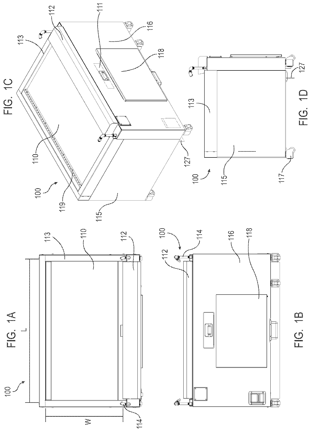
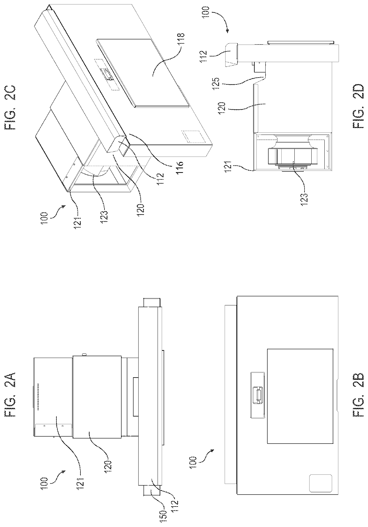
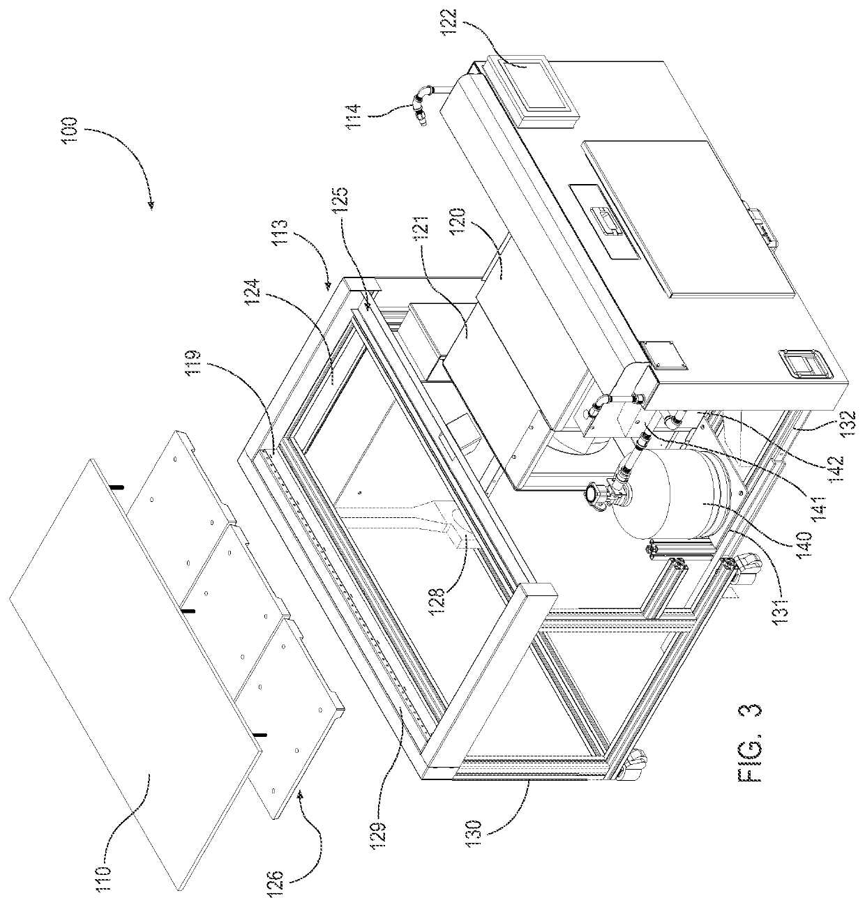
[0049]The present disclosure provides for a recirculation grill having at least one or more of the following features: (i) a diffuser and an interior plenum operable for improved air flow into a tunnel and grease control; (ii) a waste trough extending the entire or most of a length of a cooking surface and positioned beneath an aperture; (iii) a mobile platform for maneuvering and improved access to interior components of a cooking unit for cleaning and repair; (iv) a variable fan drive (VFD) for improved efficiency and control of air flow through a filter; and (v) a combination filter operable for improvement of filter waste, cleaning, and replacement. The present disclosure provides for a recirculation grill / table that can be mobile and that satisfies specific requirements in compliance with UL / ETL safety standards. Improvements over prior grills were made that are related to ease of use / maintenance, efficient heating characteristics, and a low level of sound / vibration to not disr...


PUM


Abstract

A recirculation grill that includes a cooktop and an intake aperture defining a plurality of slats configured for receiving smoke from the cooktop; an interior plenum configured to create a vacuum force to pull air and smoke from the cooktop into the intake aperture; a diffuser positioned within the plenum and extending downwardly and outwardly; a tunnel configured to receive air flow from the plenum and having at least a filter; a blower housing enclosing a variable speed blower fan configured for pulling air and smoke from the cooktop into the intake aperture and through the plenum and into the tunnel; and a variable fan drive (VFD) for controlling the variable speed blower fan and improving the life of the filter. The intake aperture, the plenum, and the blower are configured to achieve 100% visible smoke capture.

Description

CROSS REFERENCE TO RELATED APPLICATION[0001]This application claims priority to U.S. Provisional Application No. 62 / 884,014 filed Aug. 7, 2019, which is hereby incorporated herein by reference in its entirety.TECHNICAL FIELD[0002]The present disclosure relates generally to the field of indoor grills and cook tables and in particular, recirculation grills / tables.DESCRIPTION OF RELATED ART[0003]Indoor grilling for restaurants and private use is known in the art. Cooking food generates smoke. Traditionally, indoor cooking with either electric or gas as a power source requires ventilation of the smoke. This often means installation of expensive, stationary, and robust ventilation systems like fume hoods and the like. The use of fume hoods is a major burden on a heating ventilation and air conditioning (HVAC) system. These overhead hoods must be physically placed directly over a cooking surface and despite their physical position, they still fail to achieve significant smoke capture. As ...

Claims


Application Information

Patent Timeline
IPC IPC(8): F24C15/20F24C15/14
CPCF24C15/2021F24C15/14F24C15/2035F24C15/2042F24C15/101A47J37/0754A47J37/0786F24C15/322A23B4/052
Inventor PI, MING HKERN, DRAKEPI, DANIEL
Owner ANH INNOVATION LLC
Learn More