
Work machine

a work machine and work shaft technology, applied in mechanical machines/dredgers, soil shifting machines/dredgers, constructions, etc., can solve problems such as turning a machine body into an unstable state, and achieve the effect of suppressing a machine body

Pending Publication Date: 2021-02-18
NIHON KENKI CO LTD
View PDF0 Cites 1 Cited by
  • Summary
  • Abstract
  • Description
  • Claims
  • Application Information

AI Technical Summary

Benefits of technology

The present invention helps to keep the machine stable during switchover of control and timing. This means that the operator's actions are immediately reflected in the work device's actions, which helps to improve efficiency and accuracy.

Problems solved by technology

In the semiautomatic control of this type, if the attachment deviates from, for example, a range where the target surface is present, then the distance between the work device and the design surface becomes unclear; thus, it is considered that it is impossible or unnecessary to continue the semiautomatic control and that control over the work device is switched from the semiautomatic control to the manual control.
However, if there is a gap between a moving velocity of the attachment specified in the semiautomatic control and a moving velocity of the attachment specified in the manual control, a sudden velocity change generated at a time of switchover of control possibly turns a machine body into an unstable state.

Method used


Image

  • Work machine
  • Work machine
  • Work machine

Examples


embodiment 1

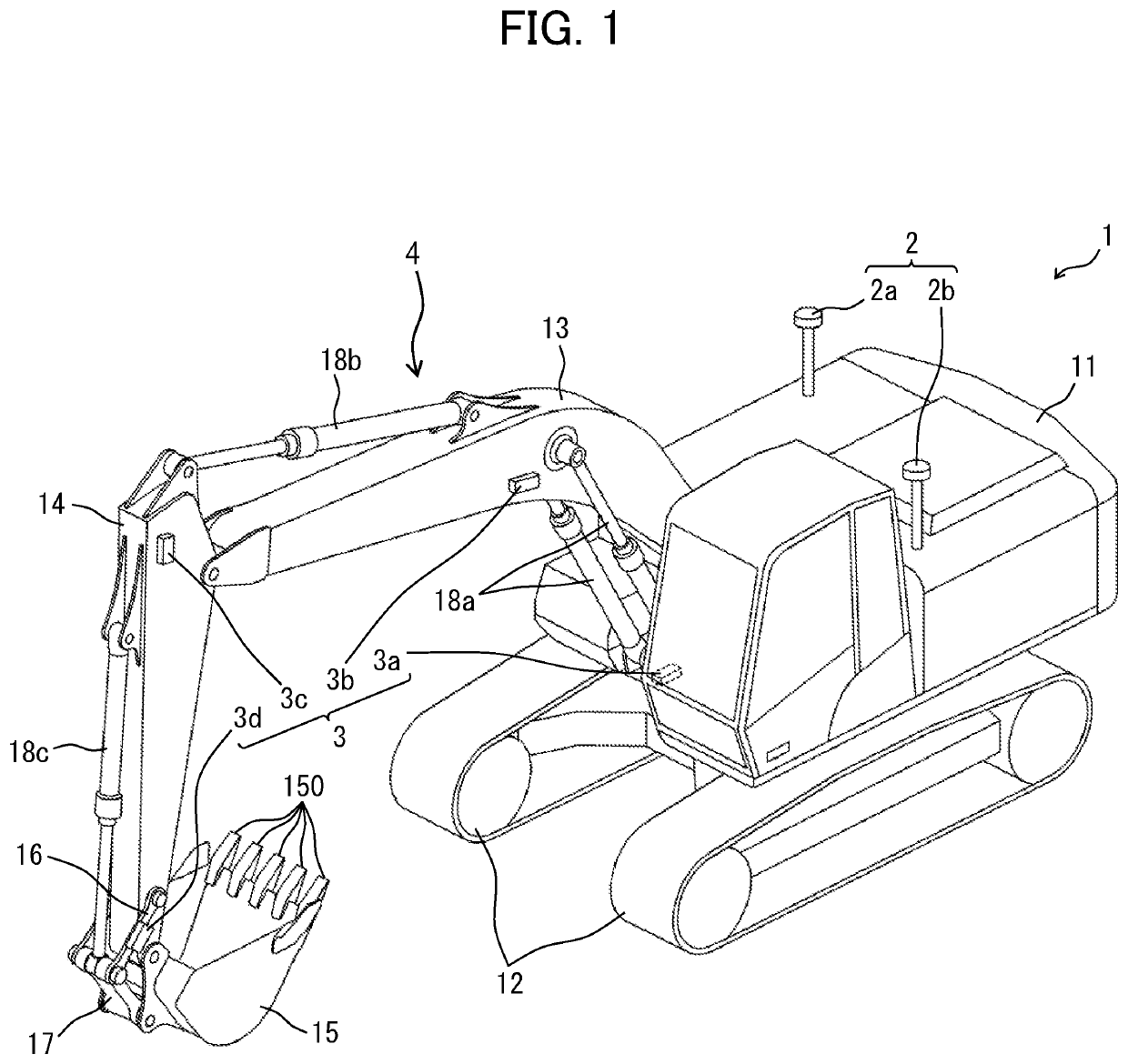
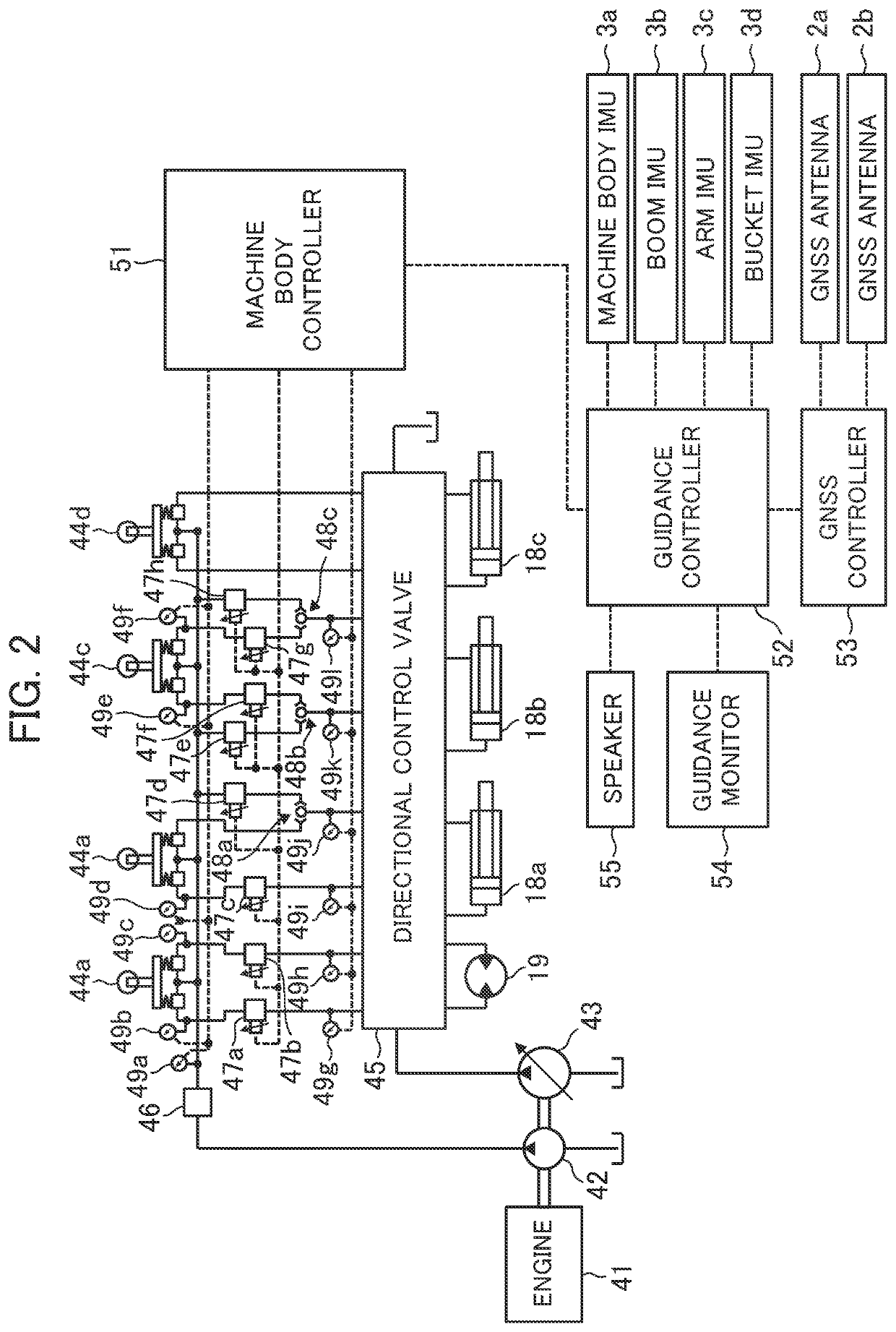
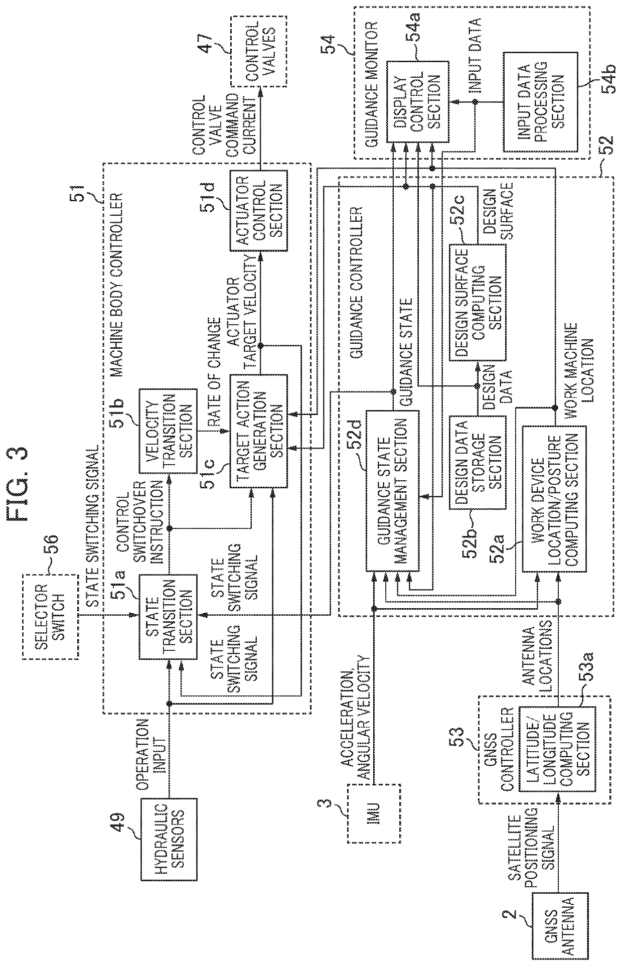
[0028]In Embodiment 1, a hydraulic excavator will be described as an example of a work machine. It is to be noted, however, that the work machine according to the present invention is not limited to the hydraulic excavator and the other work machine having a work device such as a bulldozer is also applicable as the work machine according to the present invention. A work machine according to Embodiment 1 will be described hereinafter with reference to FIGS. 1 to 7.

[0029]FIG. 1 depicts an outward appearance of the hydraulic excavator according to Embodiment 1. A hydraulic excavator 1 is configured with a lower track structure 12 including crawlers driven by a track hydraulic motor (not depicted), an upper swing structure 11 swingably attached to an upper portion of the lower track structure 12, and a multijoint work device (front work device) 4 rotatably attached to a front of the upper swing structure 11 and conducting work such as excavation. The upper swing structure 11 is driven t...

embodiment 2

[0120]Embodiment 2 of the present invention will be described with reference to FIGS. 13 to 16. It is noted that different respects from those in Embodiment 1 will be described and parts not described herein are similar to those in Embodiment 2.

[0121]FIG. 13 is a flowchart illustrating a flow of processing (velocity transition control) by the machine body controller 51 at the time of switchover from the semiautomatic control to the manual control. FIG. 13 differs from FIG. 10 in that operation determination processing is performed as an alternative to Procedure S27. In Procedure S26, the target action generation section 51c determines whether Va(t) computed in Procedure S24 or Procedure S24A is equal to Vo(t) computed in Procedure S25. In the case in which Va(t) is not equal to Vo(t), the target action generation section 51c determines a state in which the velocity transition control is still necessary, and the operation determination processing depicted in FIG. 14 is started.

[0122]...


PUM


Abstract

A controller mounted in a hydraulic excavator includes: a state transition section that performs switchover between two types of control that are manual control and semiautomatic control, on the basis of input of a state switching signal; and a velocity transition section that changes a rate of change with time in a velocity of a boom cylinder from a first rate of change I1 to a second rate of change I2 greater than the first rate of change I1 in a case in which input to an operation lever changes since the state transition section switches over between the two types of control until the velocity of the boom cylinder changes to a velocity Vo(t) specified by the control after the switchover between the two types of control.

Description

TECHNICAL FIELD[0001]The present invention relates to a work machine capable of actuating a work device in accordance with a preset condition.BACKGROUND ART[0002]Some work machines including a hydraulic excavator often have a control function (control of this type is often referred to as machine control, semiautomatic control, and the like) to acquire a position and a posture of a multijoint work device by a sensor and to cause an attachment attached to a tip end of the work device to be actuated along a target shape of an object to be worked. Such a work machine exercises manual control (often referred herein to as “first control”) to control the work device on the basis of operator's input to an operation device (for example, operation lever) similarly to other ordinary work machines, and semiautomatic control (often referred herein to as “second control”) to control the work device in accordance with a predetermined condition either irrespectively of an operator's operation on th...

Claims


Application Information

Patent Timeline
IPC IPC(8): E02F9/26E02F3/43E02F9/20E02F9/22
CPCE02F9/268E02F3/43E02F9/2004E02F3/32E02F9/2041E02F9/262E02F9/2285E02F9/2203E02F9/2296E02F9/2207E02F3/435E02F9/2025E02F9/2228E02F9/2292
Inventor YAMADA, HIROYUKIUJI, KATSUMASA
Owner NIHON KENKI CO LTD
Learn More