Display device

Pending Publication Date: 2021-02-18
SHARP KK
View PDF0 Cites 4 Cited by
  • Summary
  • Abstract
  • Description
  • Claims
  • Application Information

AI Technical Summary

Benefits of technology

The patent text describes a display panel with an irregularly shaped area where data lines and circuits are formed. The data lines are arranged along the outer edge of the display area, and the circuit blocks, including scan circuits and emission circuits, are formed in the circuit area. The number of data lines decreases as the distance from the terminal portion increases, which results in a narrower data line area and a wider circuit area. This allows for an increase in the number of unit circuit blocks while maintaining a narrow frame area. This design prevents the curvature portion near the terminal portion from becoming wider and allows for a more efficient use of space.

Problems solved by technology

However, in the case of the irregularly shaped panel, it is often required to dispose a driver circuit not only in a straight frame area but also in a curved frame area, and this demands narrowing the curved frame area.

Method used


Image

  • Display device
  • Display device
  • Display device

Examples


first embodiment

1. First Embodiment

1.1 Configuration of the Organic El Display Device

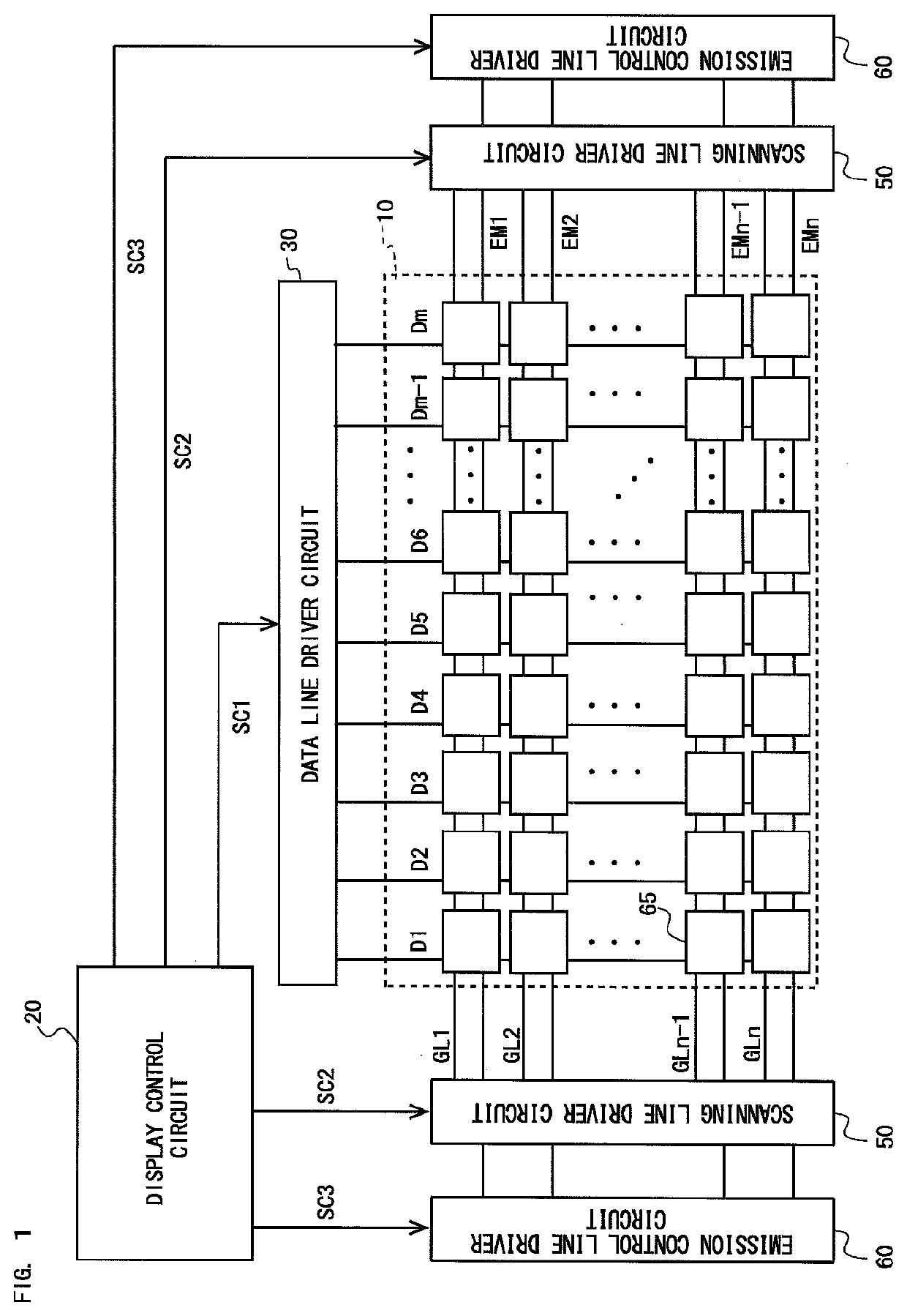
[0035]FIG. 1 is a block diagram illustrating the configuration of an organic EL display device according to a first embodiment. As shown in FIG. 1, the organic EL display device (referred to below simply as the “display device”) includes a display panel 10, a display control circuit 20, a data line driver circuit 30, scanning line driver circuits 50, and emission control line driver circuits 60. The numbers of scanning line driver circuits 50 and emission control line driver circuits 60 are both two, and these circuits are arranged one each on either side of the display panel 10.

[0036]The display panel 10 has m (where m is an integer of 1 or more) data lines D1 to Dm arranged thereon. These data lines D1 to Dm cross n scanning lines GL1 to GLn extending between the scanning line driver circuits 50. Moreover, the n scanning lines GL1 to GLn are parallel to n emission control lines EM1 to EMn extending between the em...

second embodiment

2. Second Embodiment

[0083]The configuration and operation of an organic EL display device according to a second embodiment is the same as the configuration and operation of the organic EL display device according to the first embodiment and therefore will not be elaborated upon in the present embodiment.

2.1 Arrangement of the Scan Circuit and the Emission Circuit in the Present Embodiment

[0084]FIG. 18 is an enlarged view of the first curvature portion 12a and a surrounding portion of the display panel 10 in the present embodiment. As shown in FIG. 18, the data line area is the same as in the first embodiment shown in FIG. 14 and therefore will not be elaborated upon.

[0085]Next, the circuit area will be described. As shown in FIG. 18, there are a plurality of circuit blocks arranged along the data line dout provided outside the data line area. In the present embodiment, the slant angle of each circuit block is determined by the slant angle of the outermost data line dout adjacent to ...

third embodiment

3. Third Embodiment

[0089]The configuration and operation of an organic EL display device according to a third embodiment is the same as the configuration and operation of the organic EL display device according to the first embodiment and therefore will not be elaborated upon in the present embodiment.

3.1 Arrangement of the Scan Circuit and the Emission Circuit in the Present Embodiment

[0090]FIG. 19 is an enlarged view of the first curvature portion 12a and a surrounding portion of the display panel 10 in the present embodiment. As shown in FIG. 19, the data line area is the same as in the first embodiment and therefore will not be elaborated upon.

[0091]Next, the circuit area will be described. There are a plurality of circuit blocks arranged along the outermost data line dout. In the present embodiment, the slant angle of each circuit block is set to be approximately the same as the slant angle of a plurality of straight line segments that constitute the outermost data line dout. A...


PUM


Abstract

Provided is a display device including a display panel which allows a curvature portion thereof to be narrowed near a terminal portion even when circuit blocks are arranged in the curvature portion.For a data line in the form of a polyline consisting of a plurality of short straight line segments in a first curvature portion 12a of a display panel 10, as the distance from a terminal portion 16 increases, the slant angle of each straight line segment increases, the number of data lines d decreases, and hence the width of a data line area decreases. Accordingly, the number of unit circuit blocks 70 in a parallel circuit block 80 disposed in a circuit area can be increased by widening the circuit area in proportion to the decrease in the width of the data line area.

Description

TECHNICAL FIELD[0001]The following disclosure relates to display devices, more specifically to a display device, such as an organic EL display device, which includes electro-optic elements driven by current.BACKGROUND ART[0002]As a thin display device that achieves high picture quality, low power consumption, etc., an organic EL (electro-luminescent) display device is drawing attention and currently under active development. In the organic EL display device, a display panel on which to display an image includes a display area, in which a plurality of pixel circuits are arranged, and a frame area provided around the display area, in which a monolithic driver circuit is disposed as a driver circuit for driving the pixel circuits.[0003]In recent years, with proliferation of mobile electronic devices, display panels (irregularly shaped panels) shaped differently from conventional rectangular panels have been increasingly used in order to achieve more compact electronic devices. In some ...

Claims


Application Information

Patent Timeline
IPC IPC(8): G02F1/1345H01L27/32H05K1/18
CPCG02F1/13452H05K1/189H01L27/3244G09F9/00G09F9/30G02F2201/56G09G2300/0426G09G2300/0408G09G2310/0286G09G3/3266G09G2320/064H10K59/131H10K59/12
Inventor YAMADA, JUNICHIYOKOYAMA, MAKOTOUEDA, NAOKI
Owner SHARP KK
Why Eureka
Try Eureka