
Methods, Inhalation Device, and Computer Program

a technology of which is applied in the field of methods, inhalation device and computer program, can solve the problems of simply setting pre-heating power (wattage) and time constraints, unsatisfactory heating of heating elements, and course unacceptable and possibly dangerous, and achieve accurate control, slow activation, and incomplete and/or highly variable aerosolisations.

Pending Publication Date: 2021-02-25
VENTUS MEDICAL LTD
View PDF9 Cites 12 Cited by
  • Summary
  • Abstract
  • Description
  • Claims
  • Application Information

AI Technical Summary

Benefits of technology

The invention relates to an inhalation device that can control the amount and quality of aerosolized composition delivered to the user. By measuring the ambient temperature and adjusting the power delivered to the heating element, the device can ensure consistent and accurate heating and cooling, resulting in a reliable and consistent amount of aerosolized composition being delivered each time the device is used. The invention also allows for flexibility in the quantity and quality of aerosols created, reducing the risk of excess or harmful by-products being produced. Additionally, the control software can reduce the size and complexity of the device, potentially making it more portable and user-friendly.

Problems solved by technology

To expand further, it will be appreciated that merely setting pre-heat power (wattage) and time constraints (as is possible on some more advanced devices) is insufficient because applying a set amount of power for a set amount of time will always cause the temperature of heating element to rise by a correspondingly set amount.
If ambient temperature is already elevated, it is possible that the so-called pre-heat function could actually elevate the heating element temperature above the aerosolisation temperature, which is of course unacceptable and possibly dangerous if little or no aerosolisable composition remains.
Conversely, if current ambient temperature is significantly reduced, for example in habitually cold climates, delivering a set amount of power for a set amount of time will only result in unsatisfactory warming of the heating element, resulting in slower activations, and possibly incomplete and / or highly variable aerosolisations.

Method used


Image

  • Methods, Inhalation Device, and Computer Program
  • Methods, Inhalation Device, and Computer Program
  • Methods, Inhalation Device, and Computer Program

Examples


Embodiment Construction

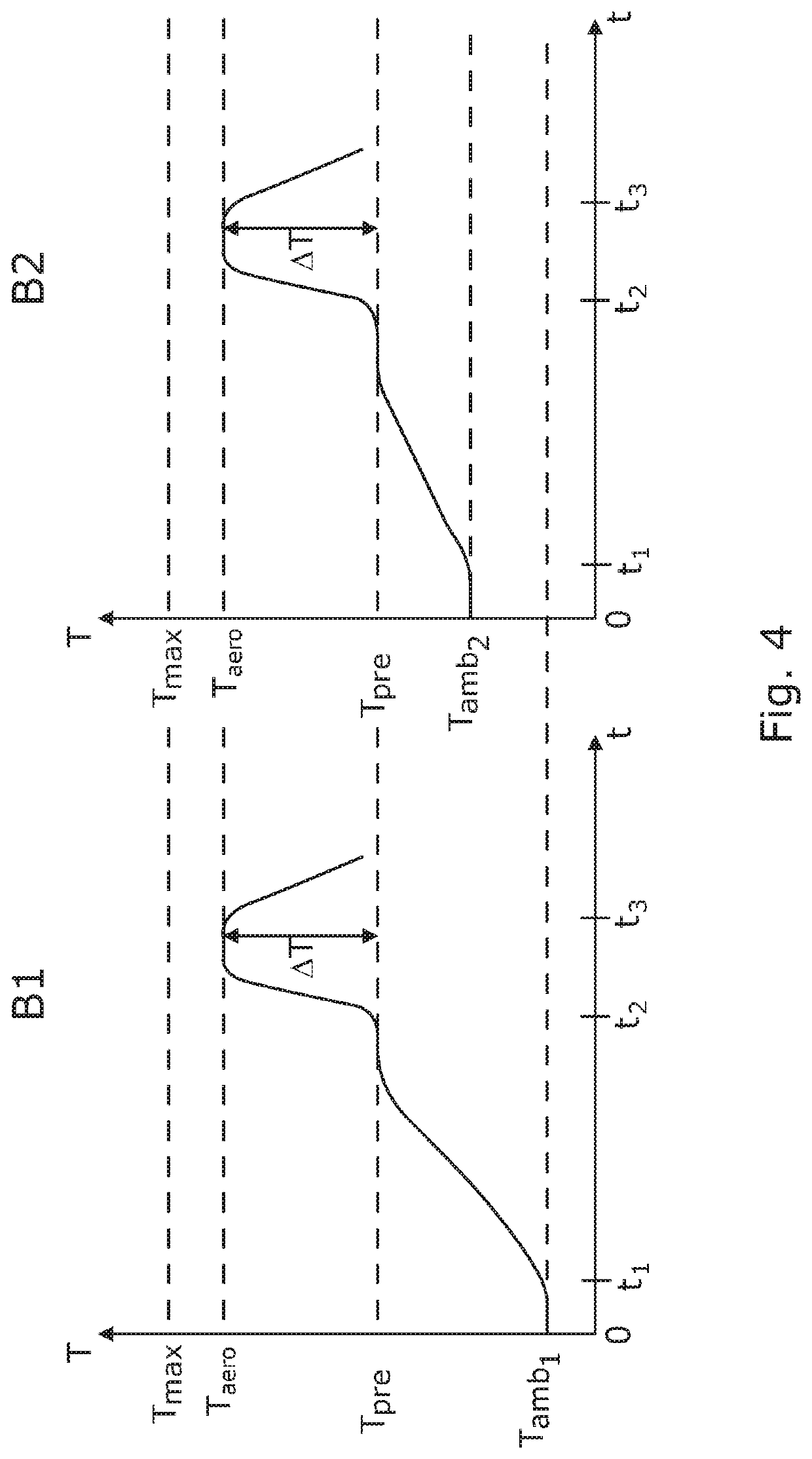
[0082]FIG. 4 shows a comparison of two separate heating profiles B1 and B2 for a heater of an inhalation device, which profiles are produced by a method according to the present invention. The heater is arranged to heat an aerosolisable composition. Each heating profile starts from a different ambient temperature Tamb1 and Tamb2 and are not drawn to scale.

[0083]In both heating profiles B1 and B2, a heater is initially heated to a first temperature or preconditioning temperature Tpre. The preconditioning temperature Tpre is the same in both heating profiles regardless of the starting ambient temperatures and may typically be in the range 5° C. to 45° C. higher than the ambient temperature, depending of course on ambient temperature norms for the particle climate, country or region in which the device is to be used. The preconditioning temperature Tpre is preferably one of the ranges 25° C. to 90° C., 35° C. to 80° C., 45° C. to 70° C.

[0084]The heater starts heating, notably relativel...


PUM


Abstract

A method of controlling the generation of an aerosolised composition in an inhalation device having a heater arranged to heat an aerosolisable composition, the method comprising: controlling the power delivered to the heater such that the heater is heated from an ambient temperature to a first temperature, wherein the first temperature is below a temperature at which the aerosolisable composition is aerosolised; delivering a predetermined amount of power to the heater such that the temperature of the heater is increased from the first temperature to a second temperature, wherein the second temperature is greater than or equal to a temperature at which at least a portion of the aerosolisable composition is aerosolised.

Description

CROSS-REFERENCE TO RELATED APPLICATIONS[0001]This application is a national stage application of International Application No. PCT / EP2019 / 050538 filed on Jan. 10, 2019, which claims priority to UK Application Nos. GB1800875.5 filed on Jan. 19, 2018 and GB1817440.9 filed on Oct. 26, 2018, which are incorporated by reference in their entireties.FIELD[0002]The present invention relates to a method of controlling the generation of an aerosolised composition in an inhalation device having a heater arranged to heat an aerosolisable composition. The present invention also relates to an inhalation device and a computer program operative in a programmable controller for an inhalation device for carrying out the method.BACKGROUND[0003]Pharmaceutical medicaments, physiologically active substances and flavourings for example may be delivered to the human body by inhalation through the mouth and / or nose. Such materials or substances may be delivered directly to the mucosa or mucous membrane lini...

Claims


Application Information

Patent Timeline
Patent Type & Authority Applications(United States)
IPC IPC(8): A61M11/04A61M15/06A24F40/10A24F40/53
CPCA61M11/042A61M15/06A61M2205/3368A61M2205/8206A61M2205/3653A61M2205/0211A61M2205/52A61M2205/50A24F40/10A24F40/53A61M2205/3372A24F40/50A24F40/46A24F40/42A24F40/57A24F40/51H02J7/007192H05B1/02H05B3/20H05B3/748A24F40/65
Inventor DIGNUM, MARKLAWSON, DAVID
Owner VENTUS MEDICAL LTD
Learn More