
Transport bag for suspended conveyor systems

a conveyor system and transport bag technology, applied in mechanical conveyors, sacks, packaging, etc., can solve the problems of limited carrying capacity of transport bags, slow and cost-intensive, and inability to fill from abov

Active Publication Date: 2021-02-25
FERAG AG
View PDF0 Cites 4 Cited by
  • Summary
  • Abstract
  • Description
  • Claims
  • Application Information

AI Technical Summary

Benefits of technology

The invention is a transfer device for transferring units of goods into and out of conveyor units of a suspended conveyor system. The device should have small volume, low energy requirements, low likelihood of failure, and minimal maintenance costs. The carrying hook of the conveyor member is designed in such a way that it can be rotated to align with two different planes, allowing for stable bearing positions and efficient transfer of the suspended transport member. The suspension hook can be transferred back and forth between the two bearing positions by rotating the conveyor member.

Problems solved by technology

A manual insertion of the units of goods into the transport members or removal of the units of goods from the transport members allows a flexible handling of different units of goods but is slow and cost-intensive.
Filling from above is not possible as the upper opening of the transport bag is not accessible due to the running rail of the conveyor system.
Due to the manner in which the transport bag is firmly fixed in the filling position, the possible carrying capacity of a transport bag is limited, as otherwise the transport bag can jam, for example due to excessive friction of the pressure plate with the skid.

Method used


Image

  • Transport bag for suspended conveyor systems
  • Transport bag for suspended conveyor systems
  • Transport bag for suspended conveyor systems

Examples


Embodiment Construction

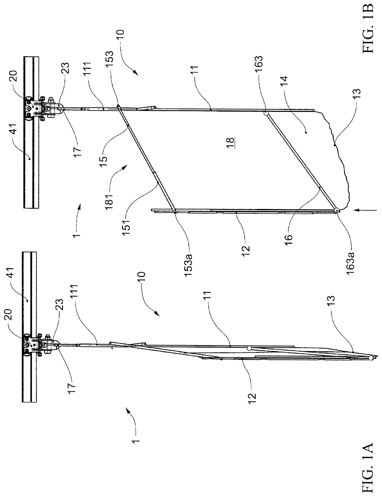
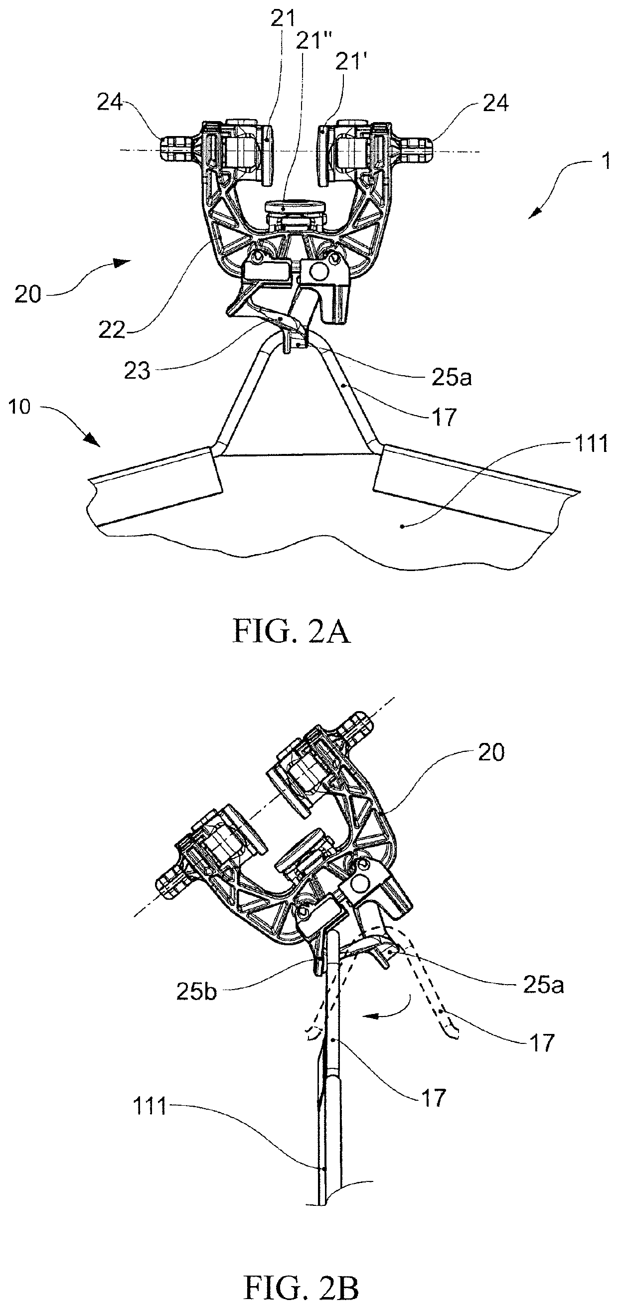
[0108]An advantageous conveyor unit 1, as it can be used in a transfer device according to the invention, is shown schematically in FIGS. 1 and 2. A carriage 20 is arranged on a running rail 41 of a rail-guided suspended conveyor system in such a manner that it can be moved by rolling A transport bag 10 is suspended from a carrying hook 23 of the carriage 20 via a suspension hook 17.

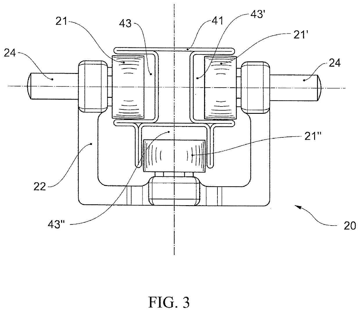
[0109]The carriage 20 has a carrying structure 22 on which three pairs of running rollers 21, 21′, 21″ are rotatably mounted. The two pairs of running rollers 21, 21′ roll in normal operation on corresponding running surfaces of the running rail 41 (not shown in FIG. 2 for clarity) and carry the weight of the conveyor unit 1. In normal operation, the pair of running rollers 21″ is arranged as a guide roller in a guide channel of the running rail 41 and absorbs radial forces when the running rail is curved in such a manner that a tilting of the carriage 20 is avoided. On the carrying structure 22 of the c...


PUM


Abstract

A transport bag (10) for a suspended conveyor system, particularly a rail-guided conveyor system or a transport chain conveyor system, has a conveyor member, particularly a carriage (20) of a rail-guided (41) conveyor system or a conveyor chain link of a transport chain conveyor system, and a transport bag (10) having a receiving region for receiving one or a plurality of units of goods (91). The transport bag is attached, via a suspension means (17), in a suspended manner to a carrying means (23) of the conveyor member. The transport bag has two frame brackets (15, 16) which are pivotally connected to the suspension means. The two frame brackets (15, 16) are substantially 2-fold rotationally symmetrical to one another, but not mirror symmetrical to one another.

Description

CROSS-REFERENCE TO RELATED APPLICATIONS[0001]Swiss Patent Application 01052 / 19, filed 22 Aug. 2019, the priority document corresponding to this invention, to which a foreign priority benefit is claimed under Title 35, United States Code, Section 119, and Title 37, United States Code, Section 1.55, and its entire teachings are incorporated, by reference, into this specification.BACKGROUND OF THE INVENTIONField of the Invention[0002]The invention relates to transport bags for a suspended conveyor system devices for transferring units of goods into conveyor units and / or out of conveyor units of a suspended conveyor system, and methods for transferring units of goods into conveyor units and / or out of conveyor units of a suspended conveyor system.Discussion of Related Art[0003]In automated warehouses, extensive production facilities and generally in the conveying and transport of goods, suspended conveyor systems have proven to be an efficient means of transport, intermediate buffering, ...

Claims


Application Information

Patent Timeline
Patent Type & Authority Applications(United States)
IPC IPC(8): B65G17/20B65G17/36B65G47/61B65G47/38
CPCB65G17/20B65G17/36B65G2201/0238B65G47/38B65G47/61B65G35/00B65D33/14B65D29/00B65G9/002B65G17/485B65G9/004B65G19/025
Inventor FENILE, ROBERTORUGE, MARTIN
Owner FERAG AG
Learn More