
Swivel Joint Type Bicycle Stand

a bicycle stand and swivel joint technology, applied in the field of bicycle stands, can solve the problems of elastic spring mechanism malfunction, device safety and maintenance concerns, safety risks, etc., and achieve the effect of minimizing potential accidents and safety risks and reducing the risk of malfunction

Inactive Publication Date: 2021-03-04
RAH HYON KYOUNG
View PDF0 Cites 1 Cited by
  • Summary
  • Abstract
  • Description
  • Claims
  • Application Information

AI Technical Summary

Benefits of technology

The present invention is a sliding bracket and mounting rack for bicycles that can fold out when needed and leave space free for other uses. It does not require a spring or elastic motion for deployment, reducing potential accidents and safety risks. The main operating components are above ground to mitigate the risk of malfunction due to infiltration or accumulation of foreign matter. Overall, the invention minimizes potential risks and improves safety for bicycle riders.

Problems solved by technology

In cases where space efficiency is a priority, this poses a problem.
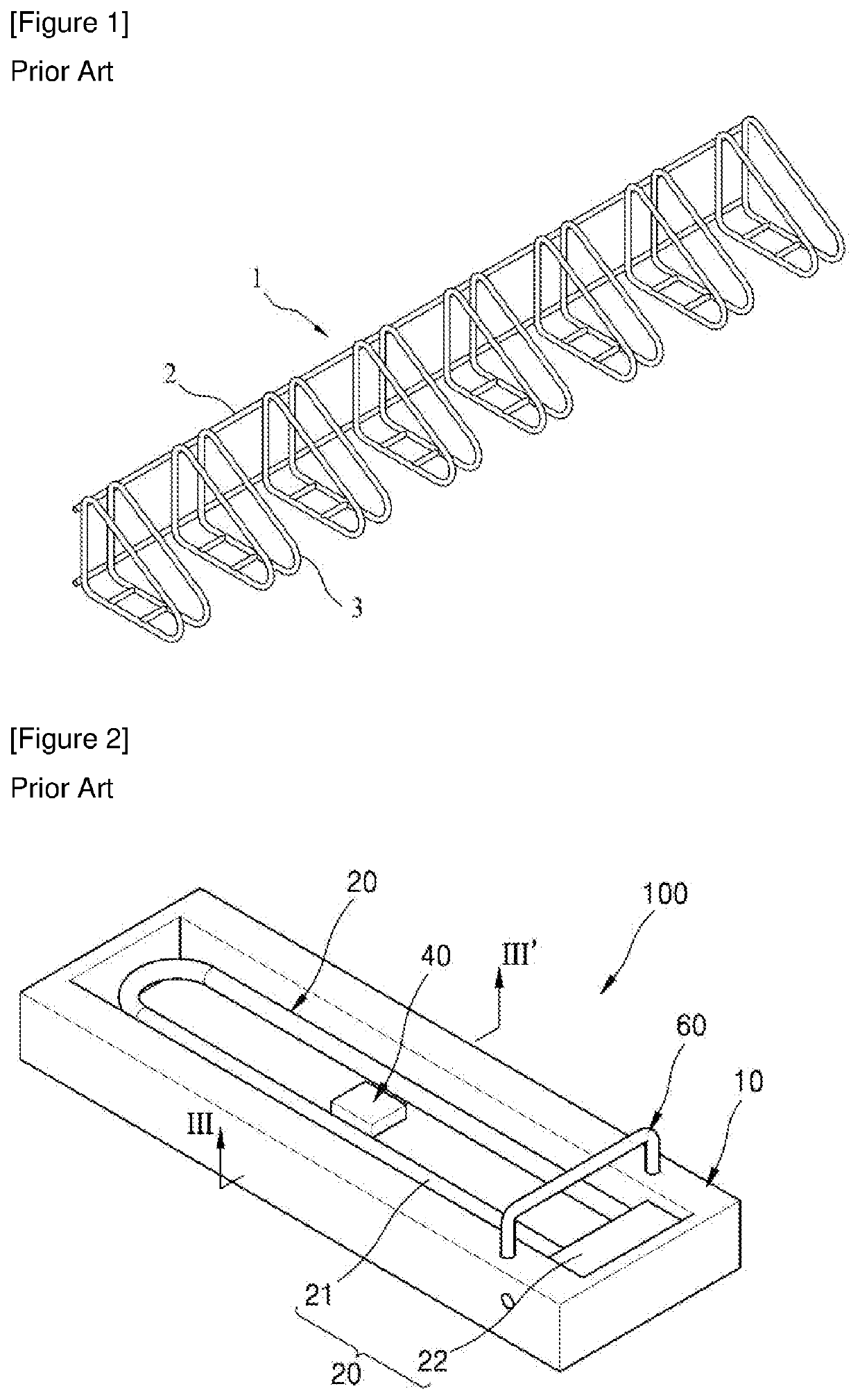
While the collapsible nature of the pivoting bracket (20) offers flexibility in the use of space, this device presents potential safety and maintenance concerns.
Any external pressure comparable to that of a wheel of a bicycle, including a foot of a pedestrian, can activate the trigger pedal (40) and cause the pivoting bracket (20) to spring up with elastic force, posing a safety risk.
Because the space inside the main bracket (10) where the pivoting bracket (20) and triggering pedal (40) rest is hollow and exposed to the elements, there is a high probability that foreign matter is introduced into this area, jamming the area around the triggering pedal (40) or otherwise causing the elastic spring mechanism to malfunction.

Method used


Image

  • Swivel Joint Type Bicycle Stand
  • Swivel Joint Type Bicycle Stand
  • Swivel Joint Type Bicycle Stand

Examples


Embodiment Construction

[0021]Hereinafter, specific embodiments of the present invention will be described in more detail with reference to the accompanying drawings.

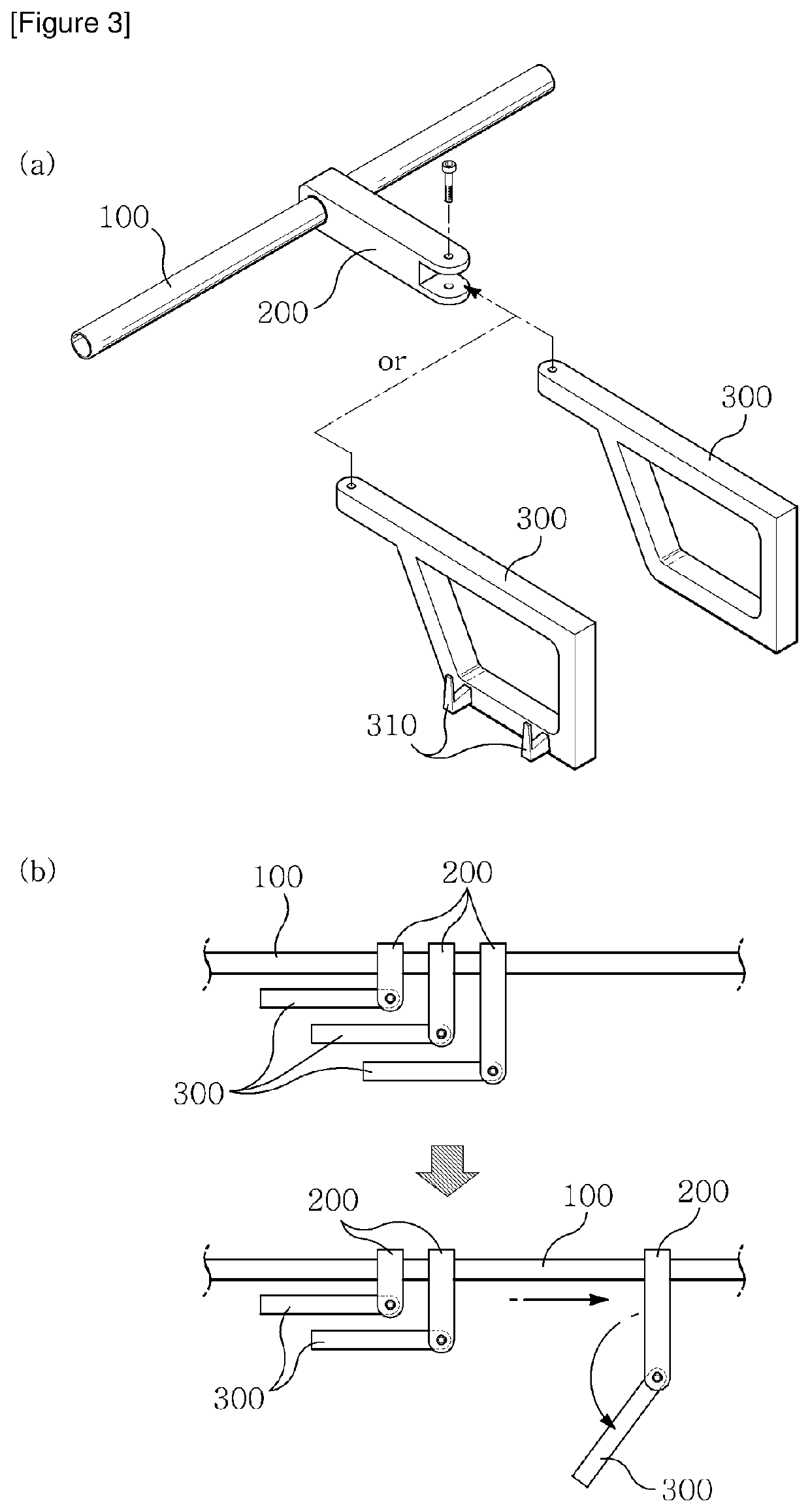
[0022]The present invention relates to a bicycle stand consisting of a main bar 100, a sliding bracket 200, and a mounting rack 300.

[0023]As shown in FIG. 3 (a), the main bar 100 is a structure installed horizontally and can be made of various cross sections of tubes, shaped steel, etc.

[0024]Although not illustrated, the ends of the main bar 100 may be installed to maintain a certain height above ground required for bicycle parking, supported by a vertical member perpendicular to the main bar 100, such as a pillar or a column.

[0025]As illustrated in FIG. 3 (a), one side of the sliding bracket 200 is slidably coupled with the main bar 100, while the mounting rack 300 is rotatably coupled with the sliding bracket 200. The sliding bracket 200 can slide along the main bar 100 with or without the mounting rack 300 rotated. The specific form and sha...


PUM


Abstract

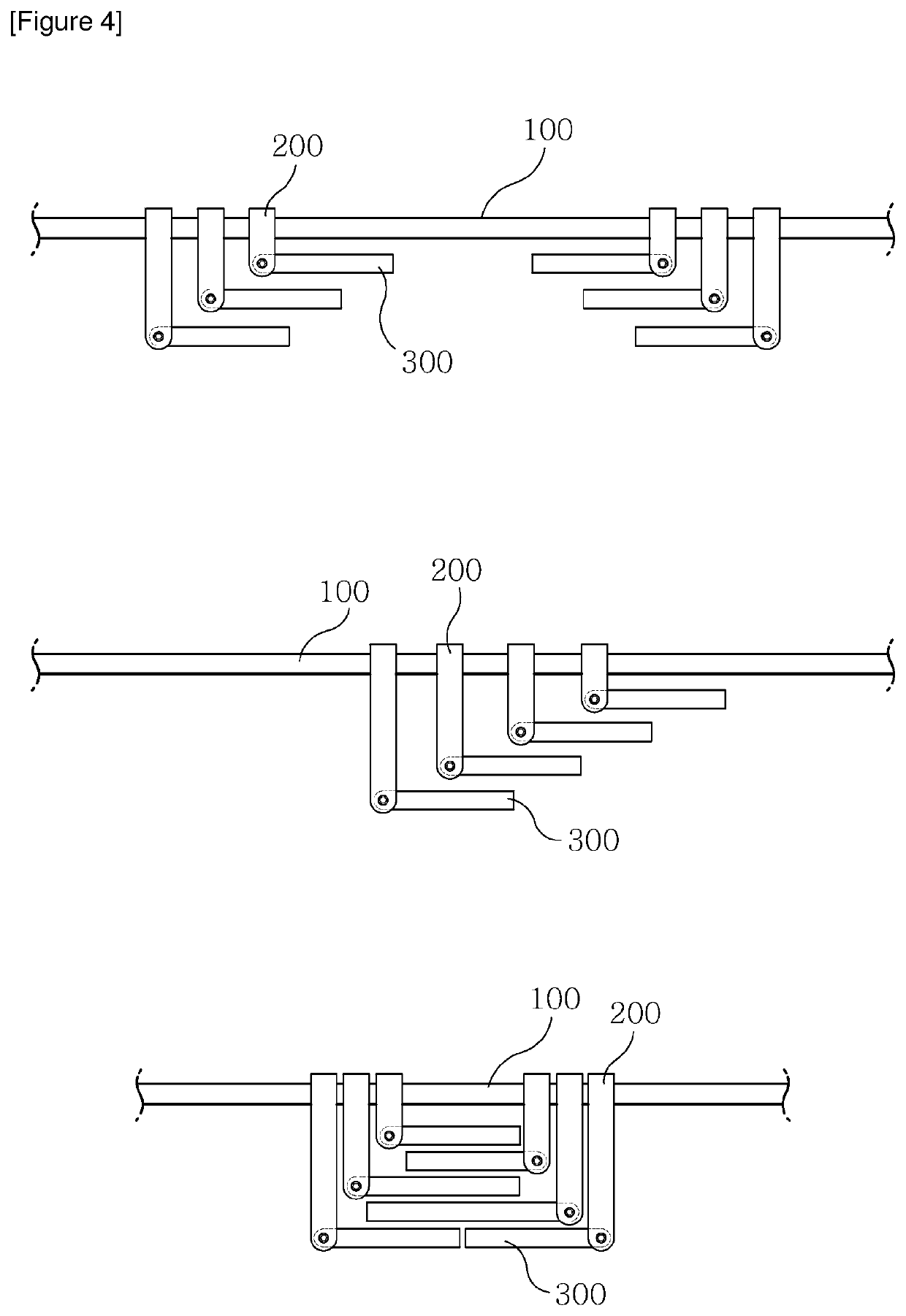
The present invention relates to a swivel join type bicycle stand, consisting of: a main bar 100 installed in a horizontal orientation, a sliding bracket 200 slidably coupled on one side with the main bar 100, and a mounting rack 300 which is rotatably coupled with the other side of the sliding bracket 200, wherein the mounting rack 300 can fold outward to accommodate bicycle parking and storage; the mounting rack 300 can be rotated inward and folded when a bicycle stand is not needed.

Description

TECHNICAL FIELD[0001]The present invention relates generally to bicycle stands and more specifically to a foldable bicycle stand with swivel joints, which can facilitate efficient use of space through folding and nesting of mounting frames that can be expanded to form a full stand when needed.DESCRIPTION OF THE PRIOR ART[0002]In recent years, increasing numbers of people have been riding bicycles to bus stops and subway stations close to their homes, storing their bicycles at transit stops to transfer to buses and subways. Installations of bicycle stands are also increasing in multi-family residential complexes and public spaces. The bicycle stand shown in FIG. 1 is a typical example.[0003]The bicycle stand (1) shown in FIG. 1 consists of a main frame (2) to fix the bicycle stand to the ground while keeping each individual mounting frame (3) spaced apart at a predetermined distance. The mounting frame (3) allows the front wheel of a bicycle to be mounted and secured.[0004]This conve...

Claims


Application Information

Patent Timeline
IPC IPC(8): B62H3/06
CPCB62H3/06B62H3/02B62H3/12B62H3/00B62H2700/00
Inventor RAH, HYON KYOUNG
Owner RAH HYON KYOUNG
Learn More