
Filtering device for damping vibrations in a conduit of a hydraulic actuation system for disengaging a clutch

Active Publication Date: 2021-03-04
RAICAM DRIVELINE SRL
View PDF0 Cites 0 Cited by
  • Summary
  • Abstract
  • Description
  • Claims
  • Application Information

AI Technical Summary

Benefits of technology

The present invention is about an improved filtering device that has lower pressure drops and is more efficient from a hydraulic perspective. The device is composed of simple shape elements that are structurally robust and easy-to-assemble.

Problems solved by technology

While driving, it may happen that the driver keeps his foot on the clutch disengagement pedal even when the pedal is not operated.
In such cases, in the absence of a filtering device, the driver may experience an annoying tingling sensation in his foot, due to close pressure waves or pulses that are transmitted as vibrations to the clutch pedal through the liquid in the pressurized conduit.

Method used


Image

  • Filtering device for damping vibrations in a conduit of a hydraulic actuation system for disengaging a clutch
  • Filtering device for damping vibrations in a conduit of a hydraulic actuation system for disengaging a clutch
  • Filtering device for damping vibrations in a conduit of a hydraulic actuation system for disengaging a clutch

Examples


Embodiment Construction

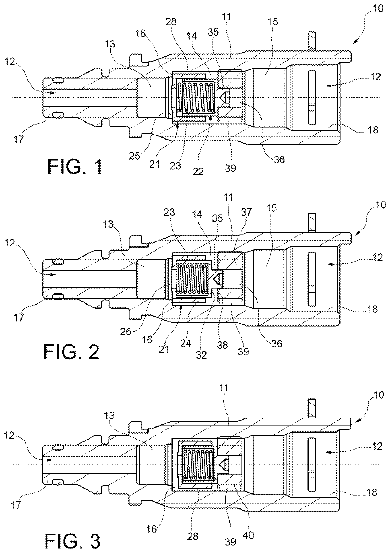
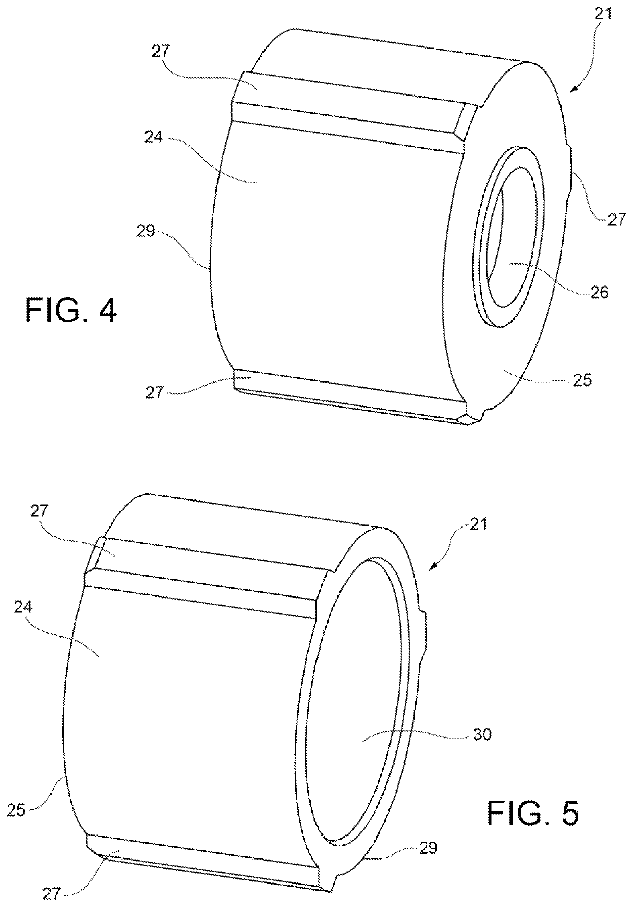
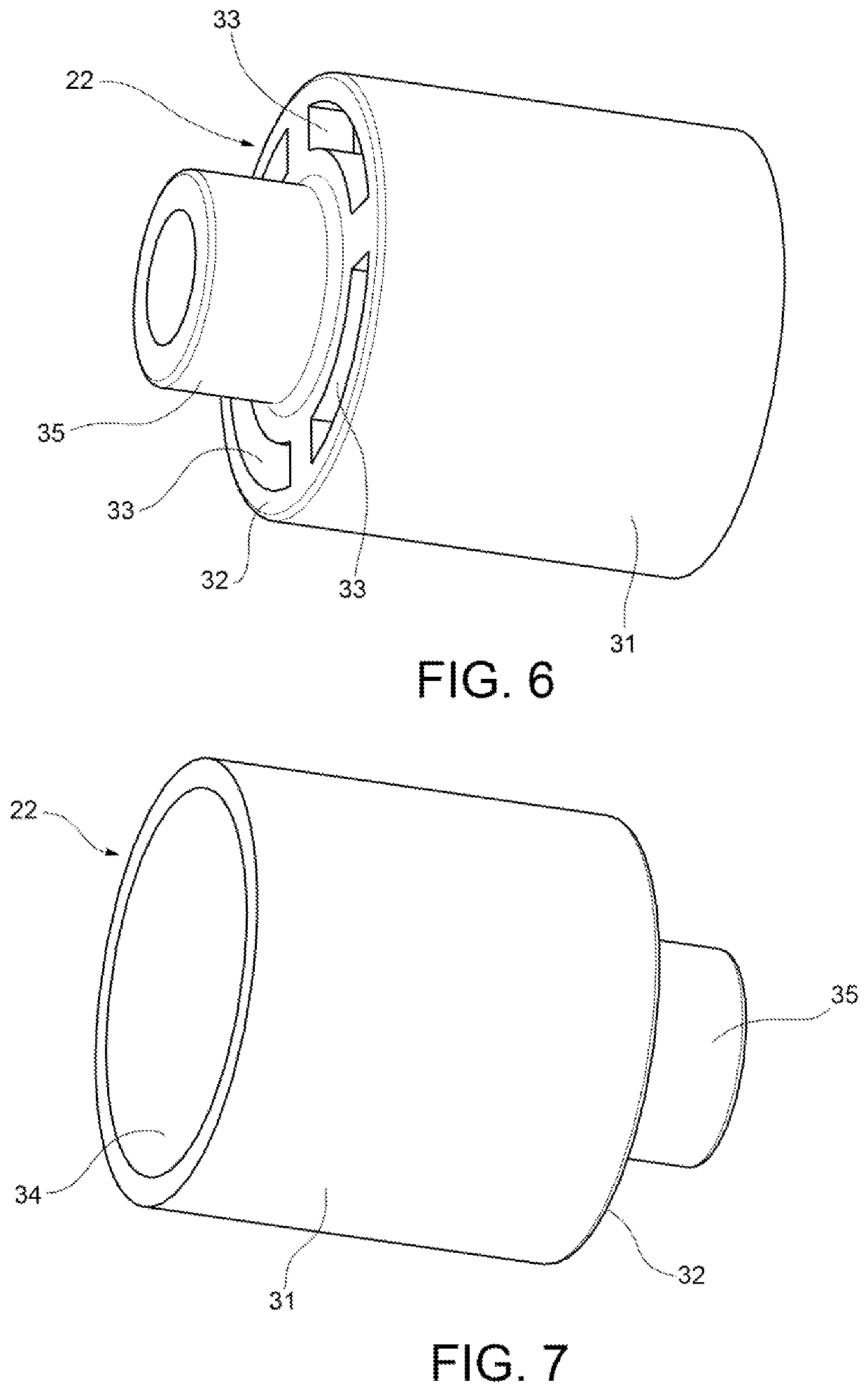
[0014]Referring initially to FIGS. 1 to 3, a filtering device according to an embodiment of the present invention is indicated as a whole at reference numeral 10. The filtering device 10 comprises an outer body 11 of tubular shape and axially elongated in a direction here defined as“longitudinal,” preferably rectilinear. It is to be understood that terms and expressions indicating directions and orientations, including “axial,”“longitudinal,”“radial” or “transversal,” are to be interpreted with reference to a longitudinal actuation axis x of the filtering device.

[0015]The outer body 11 has two opposite ends, with a first hydraulic connection 17 at a first end, to be connected, in use, to a slave cylinder (not shown) and a second end with a second hydraulic connection 18 to be connected, in use, to a master cylinder (not illustrated). In the embodiment in FIGS. 1-3, the hydraulic connection 17 on the slave side is a male connection, whereas the connection 18 on the master side is a f...


PUM


Abstract

A filtering device includes a tubular outer body with an intermediate chamber containing a pair of cup-shaped valve elements mounted floating and slidable coaxially with opposing cavities in which an axially compressed spring is housed. The first cup-shaped valve element is arranged coaxially outside the second cup-shaped valve element and has a base with a central through opening and a tubular portion with a series of ribs. The second cup-shaped valve element has a perforated base abutting against a perforated plug fixed to one side of the cavity passing towards the master cylinder. The perforated plug forms a through seat that slidably houses an appendage of the second cup-shaped valve element. Passages are formed around the plug which that establish fluid communication between the intermediate chamber and a passage to the master cylinder.

Description

CROSS-REFERENCE TO RELATED APPLICATION[0001]This application claims priority to and benefit of Italian Patent Application No. 102019000015012 filed Aug. 26, 2019, the contents of which are incorporated by reference in their entirety.FIELD OF THE INVENTION[0002]The present invention relates to a filtering device for damping vibrations, typically at low frequency, in a pressurized conduit of a hydraulic actuation system for disengaging a clutch. The filtering device is suitable to be applied in a pressurized conduit portion located between a master cylinder and a slave cylinder in the clutch disengagement system.BACKGROUND OF THE INVENTION[0003]While driving, it may happen that the driver keeps his foot on the clutch disengagement pedal even when the pedal is not operated. In such cases, in the absence of a filtering device, the driver may experience an annoying tingling sensation in his foot, due to close pressure waves or pulses that are transmitted as vibrations to the clutch pedal...

Claims


Application Information

Patent Timeline
IPC IPC(8): F16D48/02F16D25/08F16D25/12
CPCF16D48/02F16D25/08F16D25/12F16D2121/04F16D2048/0221F16D2025/081F16D2048/0215F16D25/14F15B21/008F15B21/041F16D2048/023F16D65/0006F16K15/025F16D2300/22F16K2200/301
Inventor BEDRIGNANS, JEAN BAPTISTEBOTTO, FRANCESCA
Owner RAICAM DRIVELINE SRL
Learn More