
Apparatus and system for efficiently recirculating an exhaust gas in a combustion engine

Active Publication Date: 2009-07-02
CUMMINS INC
View PDF18 Cites 5 Cited by
  • Summary
  • Abstract
  • Description
  • Claims
  • Application Information

AI Technical Summary

Benefits of technology

[0009]From the foregoing discussion, Applicant asserts that a need exists for an apparatus and system for efficiently recirculating exhaust gas in a combustion engine. Beneficially, such an apparatus and system would provide thorough mixing of EGR and intake air, with low pressure drop, in a small and simple physical package.
[0010]The present invention has been developed in response to the present state of the art, and in particular, in response to the problems and needs in the art that have not yet been fully solved by currently available methods. Accordingly, the present invention has been developed to provide an apparatus and system for efficiently recirculating an exhaust gas in a combustion engine that overcome many or all of the above-discussed shortcomings in the art.

Problems solved by technology

Blending EGR with incoming air introduces competing design constraints.
Designs which optimize the mixing of EGR and intake air often introduce significant pressure drop in the system and reduce the performance and efficiency of the engine.
Designs which optimize the pressure drop while mixing EGR and intake air often result in poor mixing and inconsistent combustion mixtures reaching each cylinder.
Additionally, the available packaging space for installing an EGR system on an engine is often low.
Some EGR systems are introduced on engine-vehicle designs that originally did not include EGR, and serious costs are incurred for any extra space consumed by the EGR system.
Even where EGR systems are designed into an original vehicle package, space constraints are often significant because increased space usage results in other tradeoffs that increase the cost of the engine and vehicle system.
Further, complicated pipe routing schemes are disfavored because such schemes introduce other constraints into the design of a vehicle system.
For example, a pipe carrying EGR gas will typically be hot, and a complex routing scheme for the pipe may limit the places where electronics and other system components can be installed in the engine compartment of a vehicle.
Additionally, a complex routing scheme for an EGR system reduces the generality of the engine-EGR design, thereby making an engine-EGR system less able to be dropped into various vehicles without significant redesign costs.
Also, complex internal routing schemes with various slots and internal conduits introduce significant machining and manufacturing costs into the system.
Further, complex routing schemes reduce transient response times due to large EGR path volumes, reduce transient performance due to inconsistent EGR compositions across the EGR path, and induce pressure drops due to long pipe lengths in the EGR path.
In a first system, a series of 90-degree straight turns in the EGR system provide some assistance in mixing and help reduce the EGR path volume, but induce significant pressure loss.
In a second system, a Venturi is used at the EGR-intake air connection point to reduce the pressure on the intake air side, but these systems provide poor mixing of EGR and intake air.
Variations of the third system may introduce added pressure drop through internal conduit flows, and introduce significant manufacturing costs into the system.

Method used


Image

  • Apparatus and system for efficiently recirculating an exhaust gas in a combustion engine
  • Apparatus and system for efficiently recirculating an exhaust gas in a combustion engine
  • Apparatus and system for efficiently recirculating an exhaust gas in a combustion engine

Examples


Embodiment Construction

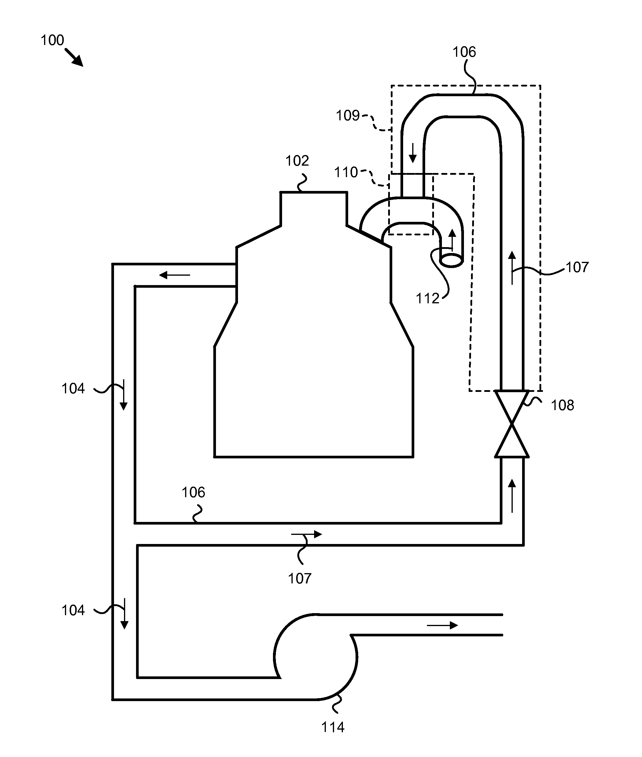
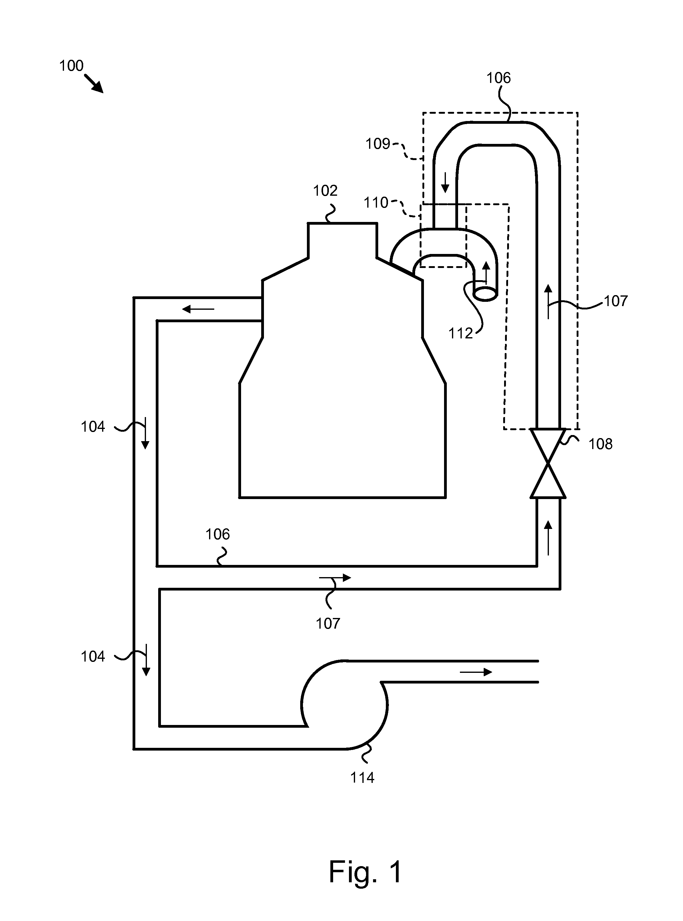
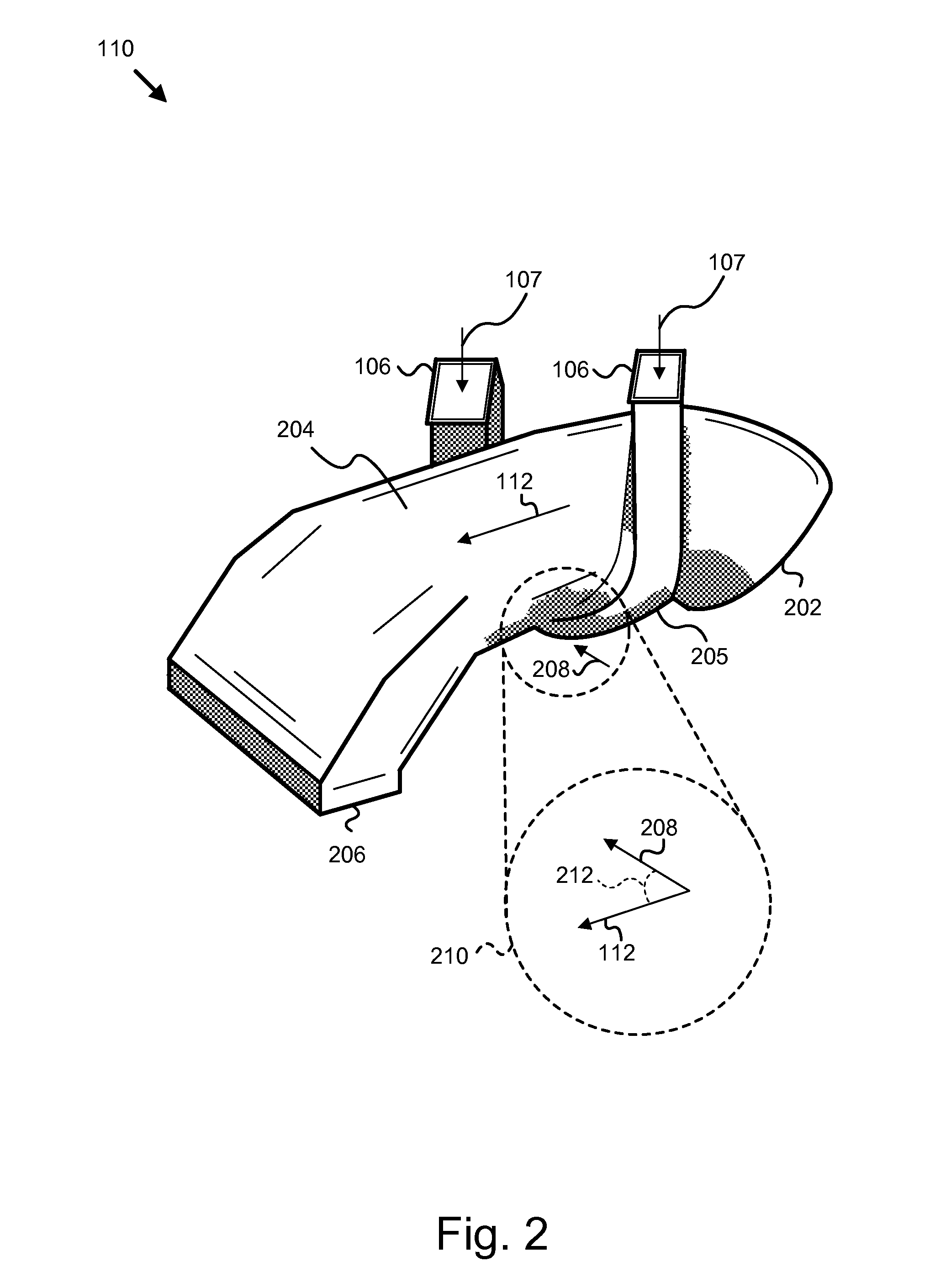
[0023]It will be readily understood that the components of the present invention, as generally described and illustrated in the figures herein, may be arranged and designed in a wide variety of different configurations. Thus, the following more detailed description of the embodiments of the apparatus and system of the present invention, as presented in FIGS. 1 through 6, is not intended to limit the scope of the invention, as claimed, but is merely representative of selected embodiments of the invention.

[0024]Reference throughout this specification to “one embodiment” or “an embodiment” means that a particular feature, structure, or characteristic described in connection with the embodiment is included in at least one embodiment of the present invention. Thus, appearances of the phrases “in one embodiment” or “in an embodiment” in various places throughout this specification are not necessarily all referring to the same embodiment.

[0025]Furthermore, the described features, structure...


PUM


Abstract

An apparatus and system are disclosed for efficiently recirculating an exhaust gas in a combustion engine. The apparatus includes an intake air conduit that accepts and promotes mixing of an intake air stream and an EGR stream. The intake air stream moves in the direction of the axis of the intake air conduit. The EGR stream enters the intake air conduit within a volute of decreasing area curled about the outside circumference of the intake air stream. The rate at which the volute encourages mixing of an EGR stream with an intake air stream is affected by the rate at which the volute's area decreases as the volute curls about the inside circumference of the intake air conduit, and by the angle of entry for the EGR stream as directed by the volute.

Description

BACKGROUND OF THE INVENTION[0001]1. Field of the Invention[0002]This invention relates to exhaust gas recirculation (EGR) systems on combustion engines, and more particularly relates to the process of mixing the EGR with intake air.[0003]2. Description of the Related Art[0004]Environmental concerns motivate emissions requirements for internal combustion engines throughout much of the world. Governmental agencies, such as the Environmental Protection Agency (EPA) in the United States, carefully monitor the emission quality of engines and set acceptable emission standards, to which all engines must comply. One important group of regulated emission components is the class of nitrogen oxides (NOx) formed during engine combustion.[0005]A system presently in use on many internal combustion engines to retard the formation of NOx is the exhaust gas recirculation (EGR) system. The EGR is mixed with air coming into the engine prior to the air entering the combustion chambers. The blending of ...

Claims


Application Information

Patent Timeline
IPC IPC(8): F02M25/07
CPCF02M25/0722Y02T10/121F02M25/0724F02M26/19F02M26/21
Inventor MATTHEWS, JEFFREY A.
Owner CUMMINS INC
Learn More