Electronic device and force sensing touch assembly thereof

Active Publication Date: 2021-03-04
ASUSTEK COMPUTER INC
View PDF0 Cites 0 Cited by
  • Summary
  • Abstract
  • Description
  • Claims
  • Application Information

AI Technical Summary

Benefits of technology

This patent describes a force touch assembly and its driving device that can detect touch in three dimensions. The assembly includes a capacitor and piezoresistive structure, which work together to acquire both two-dimensional coordinates and sense pressure. This design helps to avoid assembly misalignment issues and allows for a wide range of applications.

Problems solved by technology

However, the aforementioned architectures have the following disadvantages.
For example, the complexity of the mechanism design is increased.
When the alignment is not accurate, it will affect the accuracy of each sensing position during pressure sensing, and will also affect the accuracy and stability of the pressure value calculation.

Method used


Image

  • Electronic device and force sensing touch assembly thereof
  • Electronic device and force sensing touch assembly thereof
  • Electronic device and force sensing touch assembly thereof

Examples


Embodiment Construction

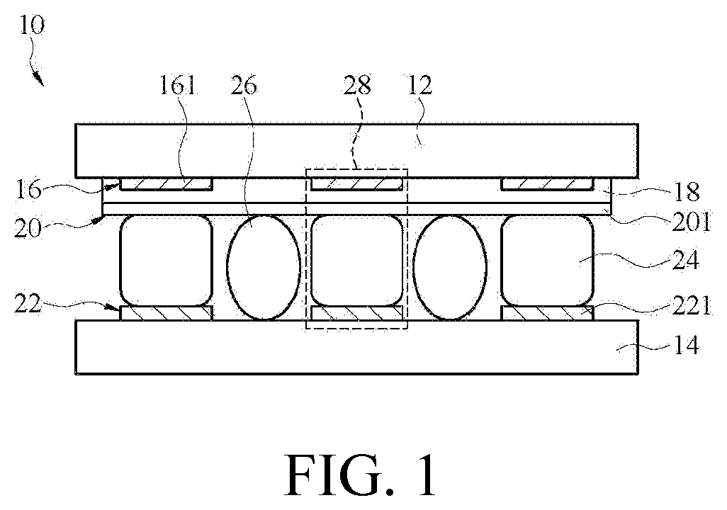
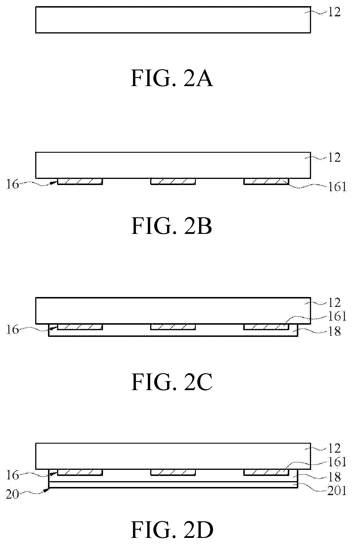
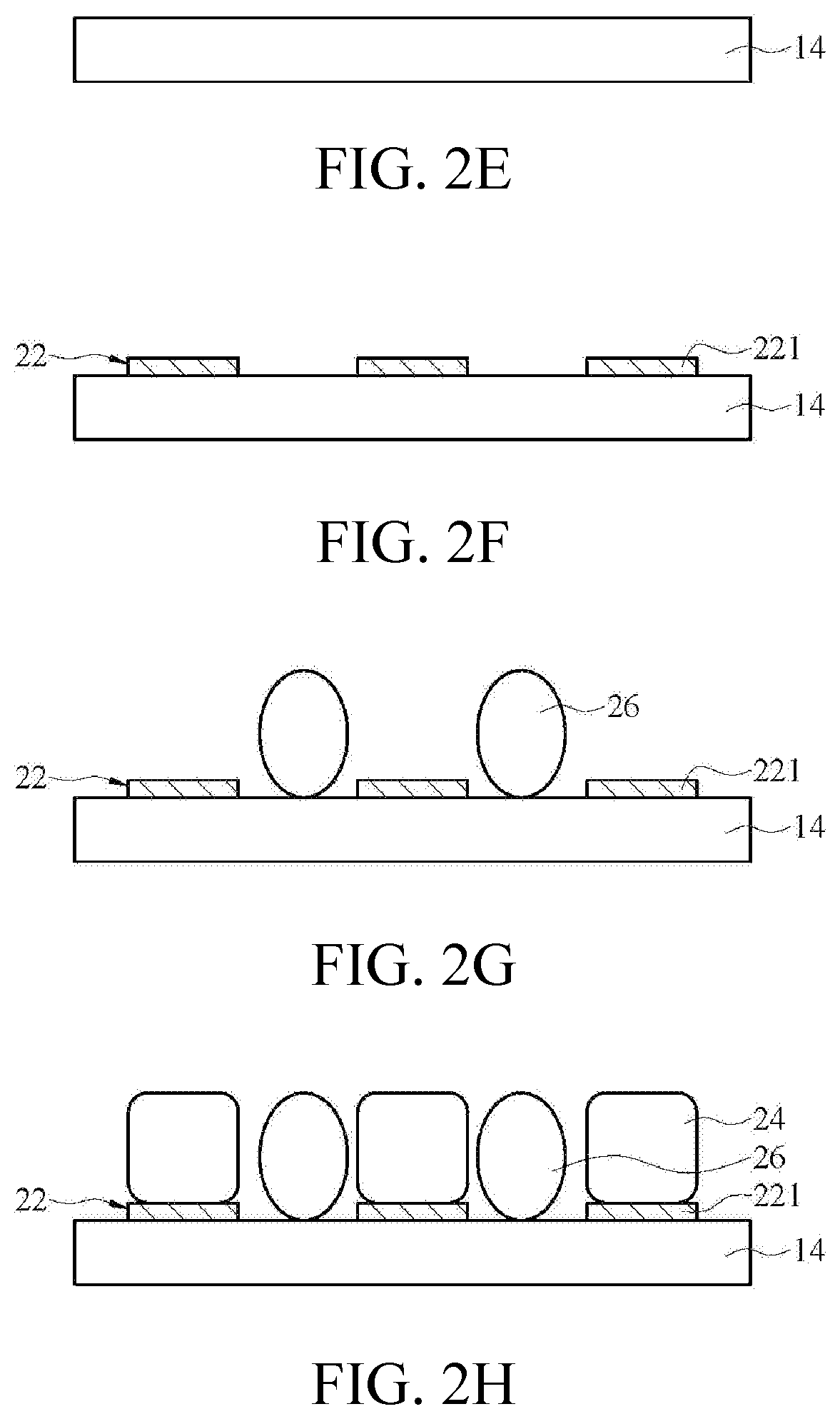
[0022]FIG. 1 is a schematic structural view of a force touch assembly of an embodiment. Please refer to FIG. 1, the force touch assembly 10 includes a first substrate 12, a second substrate 14 disposed opposite to the first substrate 12, a first patterned conductive layer 16, an insulation layer 18, a second patterned conductive layer 20, a plurality of variable pressure sensitive materials 24 and a third patterned conductive layer 22. In an embodiment, the first patterned conductive layer 16, the insulation layer 18, the second patterned conductive layer 20, the plurality of variable pressure sensitive materials 24 and the third patterned conductive layer 22 are sequentially stacked from top to bottom between the first substrate 12 and the second substrate 14. In detail, the first patterned conductive layer 16 is located on the lower surface of the first substrate 12 close to the second substrate 14. The insulation layer 18 is located on a surface of the first patterned conductive ...


PUM


Abstract

An electronic device and its force touch assembly are provided. The force touch assembly includes a first substrate, a second substrate, a first patterned conductive layer, an insulation layer, a second patterned conductive layer, a plurality of variable pressure sensitive materials and a third patterned conductive layer, wherein the first patterned conductive layer, the insulation layer, the second patterned conductive layer, the plurality of variable pressure sensitive materials and the third patterned conductive layer are sequentially stacked from top to bottom between the first substrate and the second substrate.

Description

CROSS-REFERENCE TO RELATED APPLICATION[0001]This application claims the priority benefit of Taiwan applications serial No. 108131141, filed on Aug. 29, 2019. The entirety of the above-mentioned patent application is hereby incorporated by reference herein and made a part of specification.BACKGROUND OF THE INVENTIONField of the Invention[0002]The invention relates to an electronic device and a force touch assembly thereof.Description of the Related Art[0003]Currently, there are various architectures of a force touch assembly for implementing the pressure-sensitive touch function. Some force touch assemblies adopt cantilever mechanism combined with strain gauges for pressure sensing purposes. Some force touch assemblies have a pressure sensing film between a display and a backlight module to achieve the purpose of sensing pressure (force) information through changes in capacitance. However, the aforementioned architectures have the following disadvantages. For example, the complexity ...

Claims


Application Information

Patent Timeline
IPC IPC(8): G06F3/041G06F3/044
CPCG06F3/0414G06F3/044G06F2203/04105G06F2203/04103G06F3/0412G06F3/0445
Inventor HSU, CHING-FUWONG, WEI-TINGLI, CHUN-WEILIN, HUNG-YI
Owner ASUSTEK COMPUTER INC
Why Eureka
Try Eureka