Engine controller, engine control method, and memory medium

a technology of engine control and controller, applied in the direction of electric control, machine/engine, fuel injection control, etc., can solve the problems of inaccurate detection of intake air pulsation, inability to switch appropriately, increase the detection error of air flow meter, etc., to reduce the calculation accuracy of the intake air amount of the mass flow method and reduce the detection accuracy of the intake air flow rate acquired by the air flow meter

Active Publication Date: 2021-03-11
TOYOTA JIDOSHA KK
View PDF0 Cites 0 Cited by
  • Summary
  • Abstract
  • Description
  • Claims
  • Application Information

AI Technical Summary

Benefits of technology

[0011]The first calculation process of the above-described engine controller performs the calculation of the intake air amount by the mass flow method based on the detected value of the intake air flow rate of the air flow meter. The second calculation process performs the calculation of the intake air amount by the speed density method based on the detected value of the intake pipe pressure or by the throttle speed method. When the intake air pulsation is great, the detection accuracy of the intake air flow rate acquired by the air flow meter is reduced. Accordingly, the calculation accuracy of the intake air amount of the mass flow method is reduced.

Problems solved by technology

Thus, in ranges of flow rate in which the intake air flows backward, detection errors of the air flow meter increase.
Thus, when the intake air flows backward, the magnitude of the intake air pulsation cannot be accurately detected, so that the intake air amount calculation method may fail to be switched appropriately.
Thus, when intake air pulsation that reaches a backward flow range is generated, all of the whole amplitude, the peak-side half amplitude, and the bottom-side half amplitude, which are obtained from the detection result of the air flow meter, have errors.
When an error occurs in a first intake air amount calculated value due to intake air pulsation, the relative magnitude of the error in relation to the intake air amount calculated value, rather than the absolute magnitude, may be a problem in some cases.
In this case, even if the actual intake air pulsation has not increased, the difference between the average flow rate and the minimum flow rate increases, so that it may be erroneously determined that the intake air pulsation is great.

Method used


Image

  • Engine controller, engine control method, and memory medium
  • Engine controller, engine control method, and memory medium
  • Engine controller, engine control method, and memory medium

Examples


first embodiment

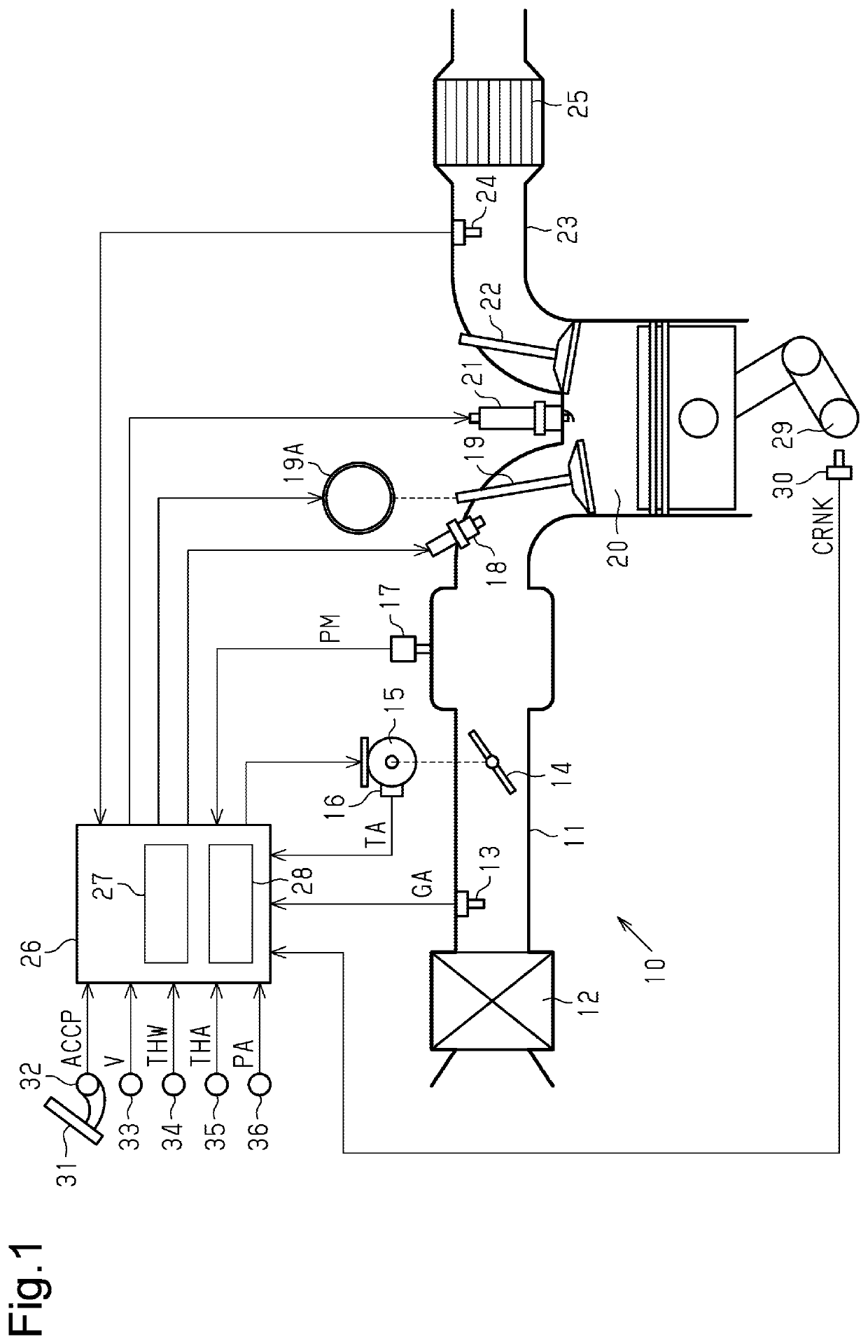
[0035]An engine controller according to a first embodiment will now be described with reference to FIGS. 1 to 4. First, the configuration of the engine controller according to the first embodiment will be described with reference to FIG. 1. The engine controller according to the first embodiment is employed in a vehicle-mounted multi-cylinder engine 10. FIG. 1 shows only one of the multiple cylinders in the engine 10.

[0036]As shown in FIG. 1, the engine 10, in which the engine controller of each embodiment is employed, includes an air cleaner 12 for filtering out dust and the like in intake air in the most upstream section of an intake passage 11. The intake passage 11 is provided with an air flow meter 13, which detects an intake air flow rate, in a section downstream of the air cleaner 12.

[0037]The intake passage 11 is provided with a throttle valve 14 in a section downstream of the air flow meter 13. The throttle valve 14 regulates the intake air flow rate. A throttle motor 15 an...

second embodiment

[0065]An engine controller according to a second embodiment will now be described with reference to FIG. 5. In the second embodiment and each embodiment described below, structures common to those of the first embodiment are identified by the same reference numbers and will not be described in detail.

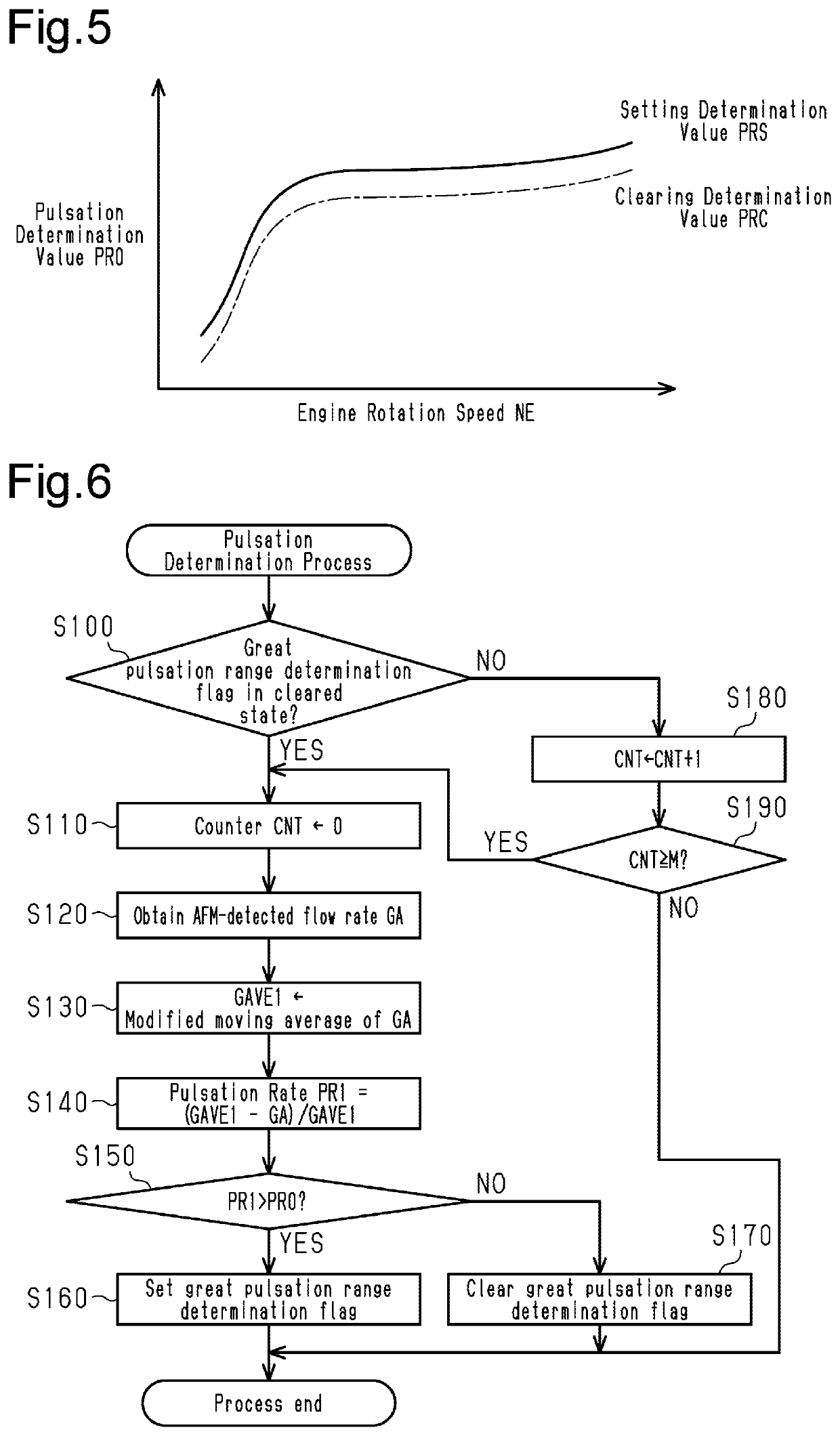
[0066]Propagation of a pressure fluctuation of intake air via the throttle valve 14 largely depends on the throttle opening degree TA. Accordingly, frequent repetitions of small changes in the throttle opening degree TA increases and decreases the intake air pulsation frequently, resulting in frequent switching of the intake air amount calculation method. This may make the engine control unstable. In this regard, the engine controller of the second embodiment sets a hysteresis for the pulsation determination value PR0 so as to reduce the frequency of switching of the intake air amount calculation method. That is, in the second embodiment, the pulsation determination value PR0 takes two ...

third embodiment

[0069]An engine controller according to a third embodiment will now be described with reference to FIGS. 6 and 7.

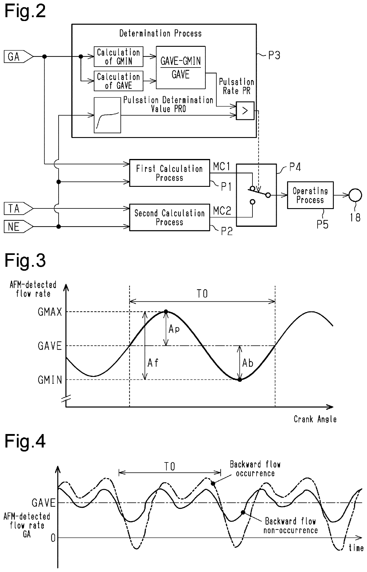
[0070]As described above, the pulsation determination is performed based on the bottom-side half amplitude Ab in the first and second embodiments. The bottom-side half amplitude Ab is calculated as the difference between the average flow rate GAVE, which is the average value of the AFM-detected flow rate GA within the period T0 of the intake air pulsation, and the minimum flow rate GMIN, which is the minimum value of the AFM-detected flow rate GA within the period T0. The average flow rate GAVE and the minimum flow rate GMIN are updated only for each period T0 of the intake air pulsation. Therefore, a temporal delay up to the amount of time corresponding to the period T0 occurs from when the intake air pulsation actually increases until the intake air amount calculation method is switched from the mass flow method to the throttle speed method. However, the third embodimen...


PUM


Abstract

An engine controller, an engine control method, and memory medium are provided. A second calculation process calculates an intake air amount without using a detection result of an air flow meter. The determination process determines that intake air pulsation is great if it is confirmed that a difference between an average flow rate and a minimum flow rate is great. The average flow rate is an average value of an intake air flow rate within a period of the intake air pulsation. The minimum flow rate is a minimum value of the intake air flow rate within the period. When it is determined that the intake air pulsation is great, a calculation method switching process selects a calculated value of the intake air amount that is obtained by the second calculation process.

Description

BACKGROUND1. Field[0001]The present disclosure relates to an engine controller that controls operation of an engine by calculating an intake air amount introduced into a cylinder and operating an actuator, such as an injector, based on the calculated value of the intake air amount.2. Description of Related Art[0002]Control of an operating state of an engine is performed by operating actuators such as injectors and a throttle valve. For example, control of an air-fuel ratio of air-fuel mixture burned in a cylinder is performed by determining a fuel injection amount required to bring the air-fuel ratio to a target value based on an intake air amount introduced into the cylinder and operating the injector to inject fuel of the determined fuel injection amount. Accurate acquisition of the intake air amount is necessary for improving the control accuracy of the above-described engine control, which is performed by determining an operation amount of the actuator based on the intake air am...

Claims


Application Information

Patent Timeline
Patent Type & Authority Applications(United States)
IPC IPC(8): F02D41/00F02D41/18
CPCF02D41/0002F02D2200/0404F02D2200/0406F02D41/18F02D41/182F02D41/34F02D2200/0402
Inventor YAMADA, TAKAFUMIANAMI, TAKAHIROKURITA, SHUNSUKE
Owner TOYOTA JIDOSHA KK
Why Eureka
Try Eureka