Filter structure capable of removing dust

Pending Publication Date: 2021-03-11
CENDORI
8 Cites 2 Cited by

AI-Extracted Technical Summary

Problems solved by technology

However, the above-described conventional air conditioner has a structure in which the filter for removing only dust introduced into the heat exchanger is installed on the side surface of the heat exchanger, but does not have any unit to block the inflow of dust into the air conditioner or to shake off or remove dust collected in the air conditioner thereby...

Method used

[0026]The upper end of the concave groove part 131 may be located under a motor shaft 161, and the lower end thereof may be located over the opening 140. The reason for this is that, when the brush 170 is rotated, the brush 170 in an upright state may be most capable of easily wiping off dust.
[0032]The concave groove part 131 coupled to the open par...

Benefits of technology

[0012]The present invention has an effect in that a dust removal unit of the brush can be continuously shaken off by the concave groove part formed on one side surface of the dust collection net, and thus, dust can be efficiently removed without being dragged by the rotated brush.
[0013]Part...

Abstract

A filter structure capable of removing dust is proposed. The filter structure includes a circular rim part; a frame, extending from the rim part, for installing a motor; a dust collection net attached to the frame; a brush which is in close contact with the dust collection net and is rotated by means of the motor; an opening, formed at a lower end of the rim part, for discharging dust; an open part formed at one side of the dust collection net; and a concave groove part having an outside coupled to the open part and in one-side communication with the opening at the rim part.

Application Domain

Technology Topic

Image

  • Filter structure capable of removing dust
  • Filter structure capable of removing dust
  • Filter structure capable of removing dust

Examples

  • Experimental program(1)

Example

BEST MODE
[0019]Hereinafter, reference will be made in detail to preferred embodiments of the present invention, examples of which are illustrated in the accompanying drawings. However, the disclosure of the invention is not limited to the embodiments set forth herein and may be variously modified. The terminology used herein is for the purpose of describing particular exemplary embodiments only and is not intended to limit the present invention. Further, as used herein, the singular forms may be intended to include the plural forms as well, unless the context clearly indicates otherwise. In the following description of the embodiments, terms, such as “comprising”, are inclusive and therefore specify the presence of stated features, integers, steps, operations, elements, and/or components, but do not preclude the presence or addition of one or more other features, integers, steps, operations, elements, components, and/or groups thereof. All terms including technical terms and scientific terms used herein have the same meanings as those understood by those skilled in the art, unless stated otherwise. Terms defined in dictionaries which are usually used are to be interpreted as having meanings coinciding with relevant technical documents and the present disclosure, and are not to be interpreted as having ideal or formal meanings, unless defined otherwise.
[0020]The embodiment of the present invention, which will be described with reference to perspective views, specifically indicate the ideal embodiment of the invention. Consequently, various modifications to what is illustrated, for example, modifications of manufacturing methods and/or specifications, can be expected. Therefore, the embodiments are not limited to the specific forms in the regions shown, and, for example, may include modifications of forms due to manufacture. For example, a region illustrated or described as being even may have a rough or rough and nonlinear property. Further, a part illustrated as having a sharp angle may be rounded. Therefore, the regions shown in the drawings are merely approximate, and the forms thereof are not intended to illustrate the correct forms of the regions, and are not intended to limit the scope of the invention.
MODE FOR INVENTION
[0021]Hereinafter, an exemplary embodiment of a dust collector for air conditioners according to the present invention will be described in detail with reference to the accompanying drawings.
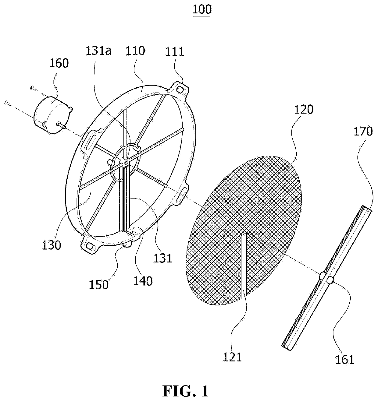
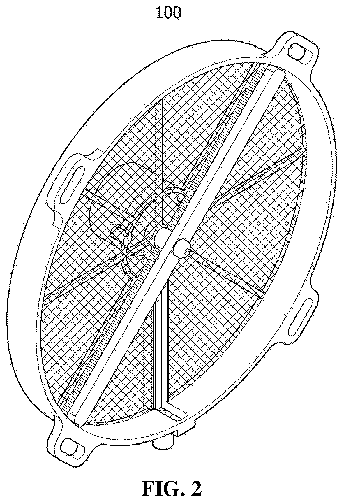
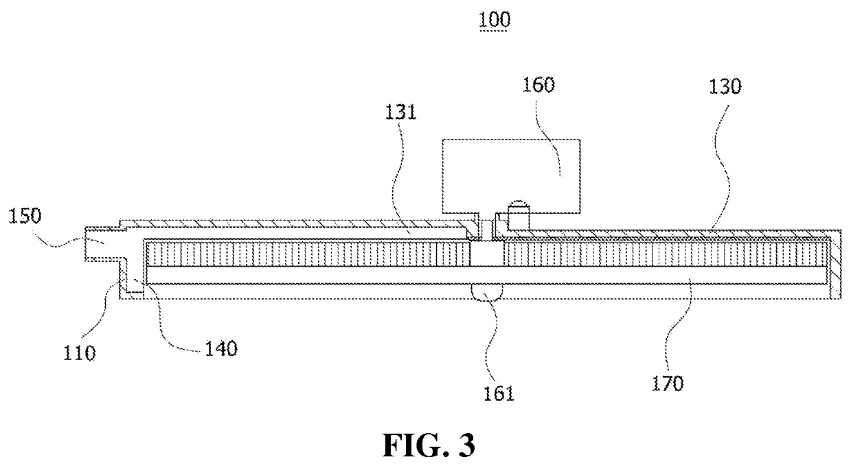
[0022]FIG. 1 is an exploded perspective view of the dust collector for air conditioners according to the present invention, FIG. 2 is a perspective view illustrating the dust collector of FIG. 1 in an assembled state, FIG. 3 is a cross-sectional view of FIG. 2, FIG. 4 is a reference view illustrating the usage state of the dust collector according to the present invention, and FIG. 5 is a cross-sectional view illustrating the usage state of the dust collector according to the present invention.
[0023]First, in the drawings, the same or similar elements are denoted by the same reference numerals even when they are depicted in different drawings. In the following description of the present invention, a detailed description of known functions and configurations incorporated herein will be omitted when it may make the subject matter of the present invention rather unclear.
[0024]A dust collector 100 for air conditioners according to one embodiment of the present invention includes a circular rim part 110, frames 130 configured to extend from the rim part 110 so as to install a motor 160 thereon, a dust collection net 120 attached to the frames 130, a brush 170 configured to be in close contact with the dust collection net 120 and to be rotated by the motor 160, an opening 140 formed at the lower end of the rim part 110 so as to discharge dust therethrough, an open part 121 formed at one side of the dust collection net 120, and a concave groove part 131 having the outside coupled to the open part 121 and one side communicating with the opening 140 of the rim part 110.
[0025]Here, the shape of the dust collection net 120 in the present invention may be a disc shape, and the reason for this is that the brush 170 must be rotated by the motor 160 so as to wipe off dust from one side surface of the dust collection net 120.
[0026]The upper end of the concave groove part 131 may be located under a motor shaft 161, and the lower end thereof may be located over the opening 140. The reason for this is that, when the brush 170 is rotated, the brush 170 in an upright state may be most capable of easily wiping off dust.
[0027]A plurality of frames 130 extends from the rim part 110, and is necessary to allow the motor 160 to be stably coupled thereto and to support the dust collection net 120.
[0028]A through hole 131a, through which the motor shaft 161 passes, is formed through the center among the frames 130.
[0029]The motor shaft 161 passing through the through hole 131a passes through the center of the dust collection net 120, and is coupled to the brush 170 rotated in the state in which the brush 170 is in close contact with the dust collection net 120.
[0030]A dust removal unit, which may remove dust from one side surface of the dust collection net 120 without damaging the dust collection net 120, may be formed at one end of the brush 170, and the dust removal unit may be formed of mohair, a soft resin plate, a rubber plate, or the like.
[0031]A coupling unit which couples the dust collector to one side of an external air inlet of an air conditioner (not shown) may be provided at the rim part 110, and when a screw is used as the coupling unit provided at the rim part 110, a screw hole, into which the screw is inserted may be formed, when a circular connector protrudes from the inside of the external air inlet, the rim part 110 may be coupled to the connector by interference fit, or the rim part 110 may be coupled to the external air inlet by engagement using known coupling and latch units, or the rim part 110 may be coupled to the external air inlet by screw combination using spiral threads formed therein. In addition, it is apparent that various other well-known coupling units may be used.
[0032]The concave groove part 131 coupled to the open part 121 of the dust collection net 120 serves to facilitate discharge of dust when the dust filtered out on one surface of the dust collection net 120 is swept by the brush 170, and a dust outlet 150 may be formed at the lower end of the opening 140 so as to discharge the collected dust to the outside of the air conditioner via a dust discharge pipe A.
[0033]Although the preferred embodiments of the present invention have been disclosed for illustrative purposes, those skilled in the art will appreciate that various modifications, additions and substitutions are possible, without departing from the scope and spirit of the invention as disclosed in the accompanying claims.
[Description of Reference Numerals and Marks] 100: dust collector for air conditioners 110: rim part 120: dust collection net 121: open part 130: frame 131: concave groove part 140: opening 150: dust outlet 160: motor 170: brush A: dust discharge pipe

PUM

no PUM

Description & Claims & Application Information

We can also present the details of the Description, Claims and Application information to help users get a comprehensive understanding of the technical details of the patent, such as background art, summary of invention, brief description of drawings, description of embodiments, and other original content. On the other hand, users can also determine the specific scope of protection of the technology through the list of claims; as well as understand the changes in the life cycle of the technology with the presentation of the patent timeline. Login to view more.

Similar technology patents

Method for reducing amyloid beta concentration in blood

ActiveUS20120031840A1Efficiently removeSolvent extractionDialysisΒ amyloidRemove blood
Owner:SCHOOL JURIDICAL PERSON FUJITA EDUCATIONAL INSTITUTION +1

Thermal De-Scaling Surfaces With Cryogenic Liquids And Gases

InactiveUS20100132747A1Simplify design and operationEfficiently removeCleaning heat-transfer devicesCleaning apparatusSolid phasesPollutant
Owner:APPLIED CRYOGENIC SOLUTIONS

Classification and recommendation of technical efficacy words

  • Efficiently remove

Hollow fiber membrane module

InactiveUS20070163942A1Efficiently removeFacilitate preventingMembranesSemi-permeable membranesMechanical engineeringHollow fiber membrane
Owner:TORAY IND INC

Anhydrous processing of methane into methane-sulfonic acid, methanol, and other compounds

InactiveUS20080161591A1Increase solubility and reaction rateEfficiently removePeroxyhydrates/peroxyacidsOrganic compound preparationWaste productionSolvent
Owner:RICHARDS ALAN K

System, apparatus and method for opening an occluded lesion

InactiveUS20080319462A1Efficiently removeIncrease flexibilityCannulasGuide wiresRotational atherectomy deviceIntroducer sheath
Owner:CARDIOVASCULAR SYST INC
Why Eureka
Try Eureka