

Stator tooth arrangement
- Summary
- Abstract
- Description
- Claims
- Application Information
AI Technical Summary
Benefits of technology
Problems solved by technology
Method used
Image

Examples
first embodiment
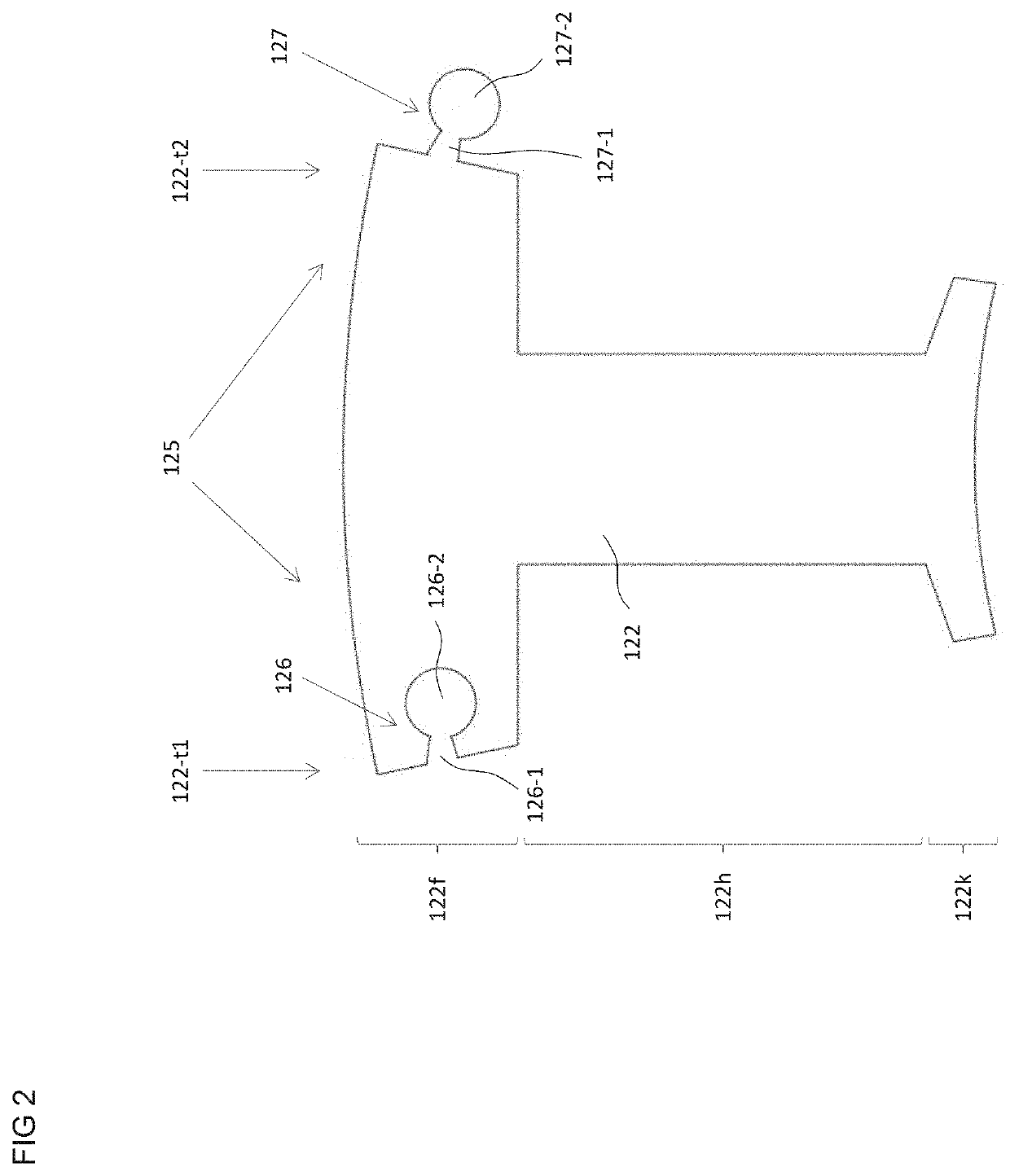
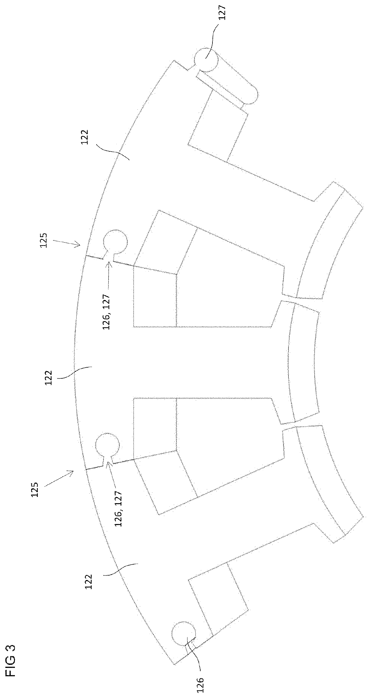
[0053]In the first embodiment, which is illustrated in FIGS. 2 and 3, the connecting device 125 is designed in the manner of a tongue and groove joint. Accordingly, each individual tooth 122 has a groove-type depression 126 and a projection 127 complementary to the depression 126. The depression 126 is arranged on one side 12241 of the two sides 122-t1, 122-t2 of the tooth root 122f, which lie opposite one another in the circumferential direction or tangential direction. The depression 126 extends into the tooth root 122f in the tangential direction. The projection 127 is arranged on the corresponding other tangential side 122-t2 of the same tooth 122 and extends away from the tooth root 122f in the tangential direction. Both the depression 126 and the projection 127 extend in the axial direction along the respective side 122-t21, 122-t2 in the tooth root region 122f of the respective individual tooth 122.
[0054]Owing to the mutually complementary designs of the depression 126 and th...
second embodiment
[0059]Owing to the mutually complementary designs of the depression 126 and the projection 127, it is also possible in the second embodiment for the projection 127 of a first individual tooth 122 to be positioned in an accurately fitting manner and so as to form a positive connection within the depression 126 of a second individual tooth 122 to be arranged adjacent to the first tooth 122. This is once again demonstrated in FIG. 5 by three individual teeth 122 arranged adjacent to one another.
[0060]In the third embodiment too, which is illustrated in FIGS. 6 and 7, it is ultimately provided, with the aid of the connecting device 125, that individual teeth 122 arranged adjacent to one another may be connected positively to one another. In order to be able to clarify the specific design of the connecting device 125 in the third embodiment, the individual tooth 122 in FIG. 6 is illustrated in perspective.
[0061]Once again, each individual tooth 122 has a depression 126 on one side 12241 ...
third embodiment
[0064]Owing to the mutually complementary designs of the depression 126 and the projection 127, it is also possible in the third embodiment for the projection 127 of a first individual tooth 122 to be positioned in an accurately fitting manner within the depression 126 of a second individual tooth 122 to be arranged adjacent to the first tooth 122. With the aid of the respective pin 128, a positive connection of the individual teeth 122 arranged in such a way relative to one another is once again ultimately formed. This is demonstrated once again in FIG. 7 by three individual teeth 122 or 122-1, 122-2, 122-3 arranged adjacent to one another, wherein the illustration shows a situation in which the pins 128 have not yet been positioned in the holes. The dashed lines merely indicate the positioning.
[0065]In the third embodiment, which is illustrated in FIGS. 6 and 7 and which, in particular, differs from the first and the second embodiment in having the additional retaining component 1...
PUM
 Abstract
Description
Claims
Application Information