
Radiation detector and radiographic imaging apparatus

Pending Publication Date: 2021-04-01
FUJIFILM CORP
View PDF1 Cites 0 Cited by
  • Summary
  • Abstract
  • Description
  • Claims
  • Application Information

AI Technical Summary

Benefits of technology

This patent describes a radiation detector and a radiographic imaging apparatus that can prevent the peeling of a layer that reflects light without affecting the quality of the image. This is achieved by using a layer with pressure-sensitive adhesiveness between the reflecting layer and the conversion layer. Additionally, the substrate used may have flexibility.

Problems solved by technology

In the above related-art radiation detector, it cannot be said that the layer having a function of reflecting light is sufficiently fixed to end parts of the substrate and the conversion layer, and there is a concern that the layer may be peeled.
In particular, in a case where the substrate has flexibility, a layer having a function of reflecting light is easily peeled off due to the bending of the substrate.
However, in a case where the pressure sensitive adhesive layer is provided between the layer having a function of reflecting light and the conversion layer, there is a concern that the image quality of a radiographic image obtained by the radiation detector may degrade.

Method used


Image

  • Radiation detector and radiographic imaging apparatus
  • Radiation detector and radiographic imaging apparatus
  • Radiation detector and radiographic imaging apparatus

Examples


first exemplary embodiment

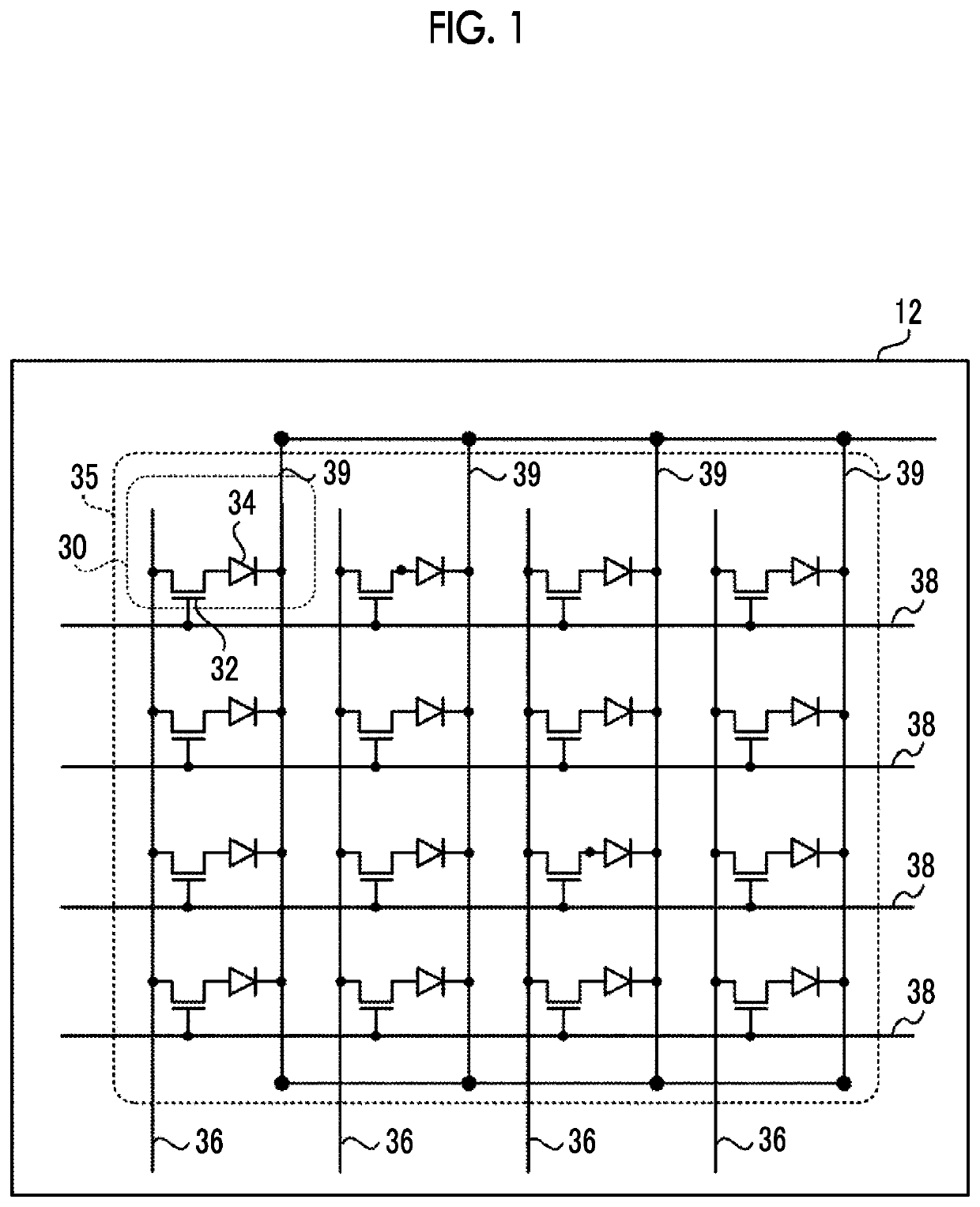
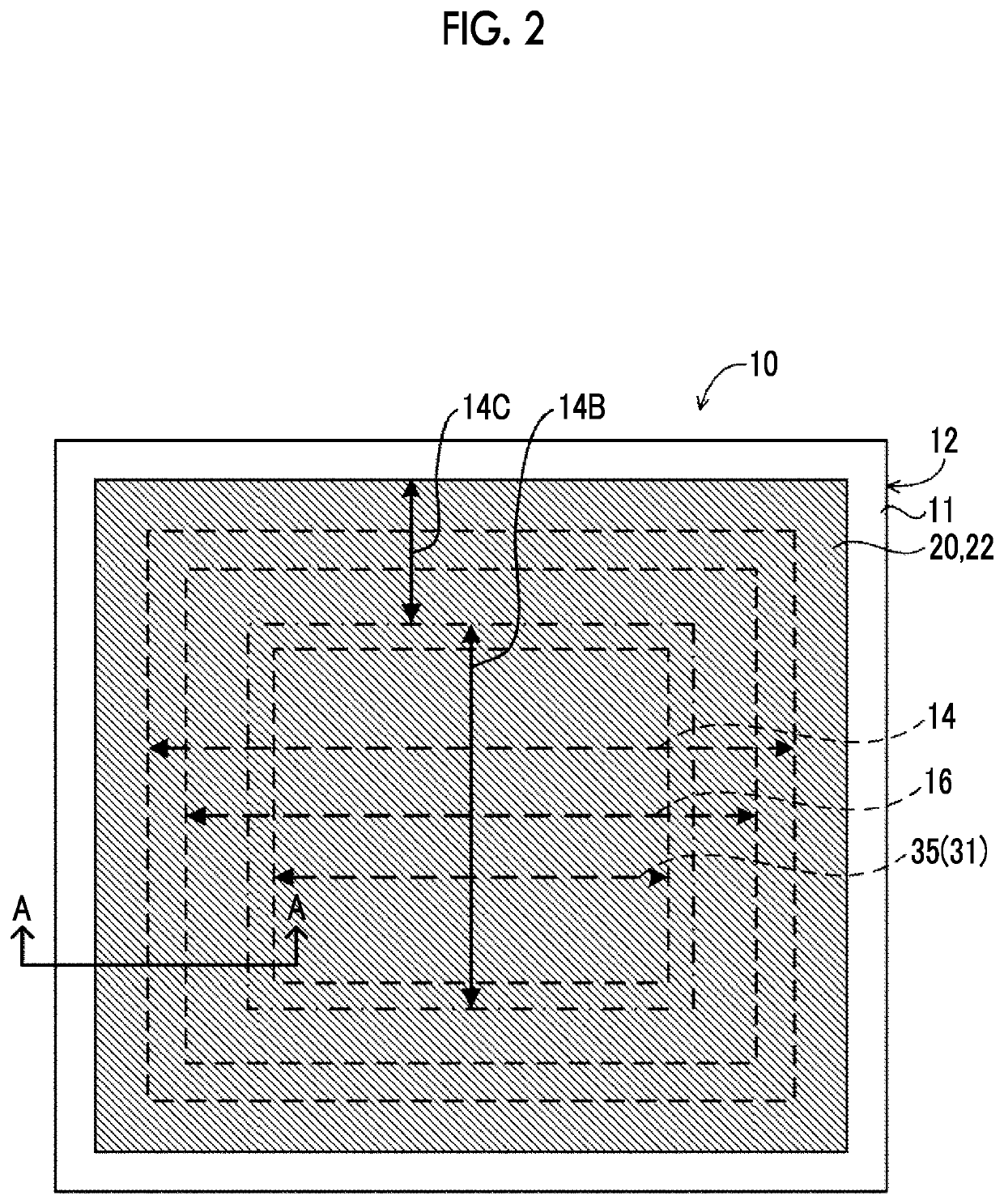
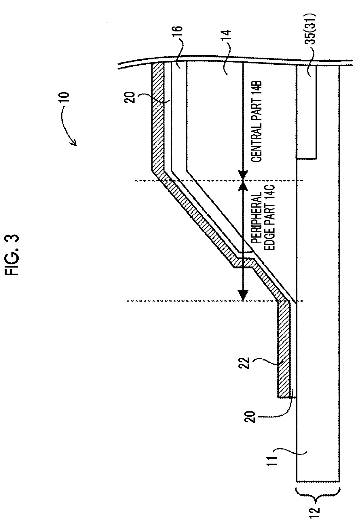
[0058]A radiation detector of the present exemplary embodiment has a function of detecting radiation transmitted through a subject to output image information representing a radiographic image of the subject. The radiation detector of the present exemplary embodiment comprises a thin film transistor (TFT) substrate, and a conversion layer that converts radiation into light (refer to a TFT substrate 12 and a conversion layer 14 of a radiation detector 10 in FIG. 3).

[0059]First, an example of the configuration of the TFT substrate 12 in the radiation detector of the present exemplary embodiment will be described with reference to FIG. 1. In addition, the TFT substrate 12 of the present exemplary embodiment is a substrate in which a pixel array 31 including a plurality of pixels 30 is formed in a pixel region 35 of a base material 11. Therefore, in the following description, the expression “the pixel region 35” is used as the same meaning as “the pixel array 31”. The TFT substrate 12 o...

second exemplary embodiment

[0101]Next, a second exemplary embodiment will be described. In addition, since the radiation detector 10 of the present exemplary embodiment is different from the first exemplary embodiment in terms of the regions where the pressure sensitive adhesive layer 16 is provided, the region where the pressure sensitive adhesive layer 16 is provided will be described with reference to the drawings.

[0102]FIG. 9 is a plan view of the radiation detector 10 of the present exemplary embodiment as seen from the side on which the conversion layer 14 is formed. Additionally, FIG. 10 is a cross-sectional view taken along line A-A of the radiation detector 10 in FIG. 9.

[0103]As illustrated in FIGS. 9 and 10, in the radiation detector 10 of the present exemplary embodiment, the pressure sensitive adhesive layer 16 is provided in the entire region on the conversion layer 14 including the central part and the peripheral edge part. In other words, the pressure sensitive adhesive layer 16 of the present ...

third exemplary embodiment

[0107]Next, a third exemplary embodiment will be described. In addition, since the radiation detector 10 of the present exemplary embodiment is different from the first exemplary embodiment in terms of a region where the adhesive layer 20 is provided, the region where the adhesive layer 20 is provided will be described with reference to the drawings.

[0108]FIG. 11 is a plan view of the radiation detector 10 of the present exemplary embodiment as seen from the side on which the conversion layer 14 is formed. Additionally, FIG. 12 is a cross-sectional view taken along line A-A of the radiation detector 10 in FIG. 11.

[0109]As illustrated in FIGS. 11 and 12, in the radiation detector 10 of the present exemplary embodiment, the adhesive layer 20 is provided on a region ranging from the TFT substrate 12 in the vicinity of the peripheral edge part of the conversion layer 14 to the outer peripheral part of the pressure sensitive adhesive layer 16. That is, in the radiation detector 10 of the...


PUM


Abstract

Provided is a radiation detector having a portion in which a substrate in which a plurality of pixels for accumulating electric charges generated in accordance with light converted from radiation are formed in a pixel region, a conversion layer that converts radiation into light, a reflective pressure sensitive adhesive layer that reflects the light converted by the conversion layer, and an adhesive layer that covering a region including a region ranging from an end part of the pressure sensitive adhesive layer to a surface of the substrate are provided in this order.

Description

CROSS-REFERENCE TO RELATED APPLICATIONS[0001]This application is a continuation application of International Application No. PCT / JP2019 / 022006, filed on Jun. 3, 2019, which is incorporated herein by reference in its entirety. Further, this application claims priority from Japanese Patent Application No. 2018-119355, filed on Jun. 22, 2018, the disclosure of which is incorporated by reference herein.BACKGROUNDTechnical Field[0002]The present disclosure relates to a radiation detector and a radiographic imaging apparatus.Related Art[0003]In the related art, radiographic imaging apparatuses that perform radiographic imaging for medical diagnosis have been known. A radiation detector for detecting radiation transmitted through a subject and generating a radiographic image is used for such radiographic imaging apparatuses.[0004]It is known that the radiation detector includes a substrate on which a plurality of pixels for accumulating electric charges generated in accordance with light c...

Claims


Application Information

Patent Timeline
IPC IPC(8): A61B6/00G01T1/20
CPCA61B6/4208G01T1/2002A61B6/4283
Inventor KATO, MUNETAKA
Owner FUJIFILM CORP
Learn More