Guide wire

a technology of guide wires and wires, applied in the direction of guide wires, etc., can solve the problems of peeled or damaged resin layers, peeling or damage of resin layers, and insufficient flexibility of guide wires, so as to reduce the power required to curve the guide wire, easy to move, and prevent peeling and damage of resin layers

Pending Publication Date: 2021-02-18
ASAHI INTECC CO LTD
View PDF0 Cites 0 Cited by
  • Summary
  • Abstract
  • Description
  • Claims
  • Application Information

AI Technical Summary

Benefits of technology

[0008]In general, when the guide wire is curved, a wire forming a coil body moves with the curve to decrease (reduce) or enlarge (expand) a space between the adjacent wires. With this configuration, the guide wire includes the resin layer extending toward the core shaft relative to the inner peripheral surface of the coil body, and thus, the thickness of the resin layer in a gap expanded with the curve of the guide wire between the adjacent wires, can be kept thick as compared to, for example, a configuration in which the resin layer is formed only on the outer peripheral surface of the coil body. Therefore, with this configuration, it is possible to suppress peeling and damage of the resin layer between the adjacent wires when the guide wire is curved. Further, with this configuration, a void is formed between the coil body and the core shaft, and thus, the wire forming the coil body easily moves as compared to a configuration having no voids, such as a case where the resin layer is formed between the wire of the coil body and the core shaft without a gap. Therefore, with this configuration, it is possible to reduce power required to curve the guide wire and improve the flexibility of the guide wire.
[0009](2) In the guide wire according to the above aspect, the protruding portion may contact the core shaft. With this configuration, the resin layer contacts the core shaft, and thus, the thickness of the resin layer in a gap expanded with the curve of the guide wire between the adjacent wires, can be kept much thicker. Thus, it is possible to further suppress peeling and damage of the resin layer when the guide wire is curved.
[0010](3) In the guide wire according to the above aspect, the protruding portion may be joined to the core shaft. With this configuration, the resin layer is joined to the core shaft, and thus, the thickness of the resin layer in a gap expanded with the curve of the guide wire between the adjacent wires, can be kept much thicker. Thus, it is possible to further suppress peeling and damage of the resin layer when the guide wire is curved.
[0011](4) The guide wire according to the above aspect further may include a resin film covering an outer peripheral surface of the core shaft, and the protruding portion may be joined to the resin film. With this configuration, the guide wire includes the resin film covering the outer peripheral surface of the core shaft, and thus, the resin film provides smoothness to improve slidability of the guide wire and to prevent foreign matters such as thrombus from adhering to the outer peripheral surface of the core shaft.
[0012](5) The guide wire according to the above aspect further may include an inner coil body formed by winding a wire around the core shaft at an inner side of the coil body. The inner coil body has a length shorter than a length of the coil body in an axial direction, and the sparsely wound part may be formed at a portion where the coil body does not cover the inner coil body. With this configuration, the sparsely wound part formed with the resin layer is located at a portion where the coil body does not cover the inner coil body, and thus, the movement of the inner coil body cannot be prevented by the resin layer. Thus, with this configuration, it is possible to maintain the flexibility of the guide wire even in the configuration including the inner coil body.

Problems solved by technology

However, the guide wire described in JP 5526218 has a problem that a resin layer is formed between a coil body and a core shaft without a gap, and thus, the flexibility of the guide wire is not sufficient.
Further, the guide wire described in JP 2008-237621 has a problem that a resin layer may be peeled or damaged when a guide wire is curved.
In the guide wire described in JP 2008-237621, the resin layer is formed on an outer peripheral surface of the coil body, and thus, the thickness of the resin layer is reduced by the resin layer being elongated in a gap expanded between two adjacent lines of a wire, which may lead to peeling or damage of the resin layer.
With this configuration, the sparsely wound part formed with the resin layer is located at a portion where the coil body does not cover the inner coil body, and thus, the movement of the inner coil body cannot be prevented by the resin layer.

Method used


Image

  • Guide wire
  • Guide wire
  • Guide wire

Examples


first embodiment

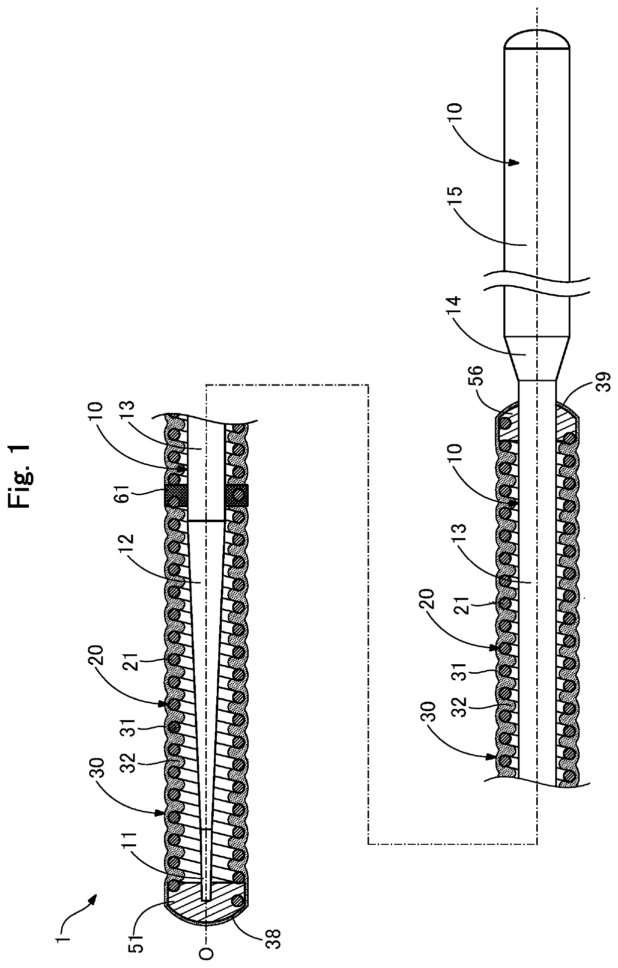
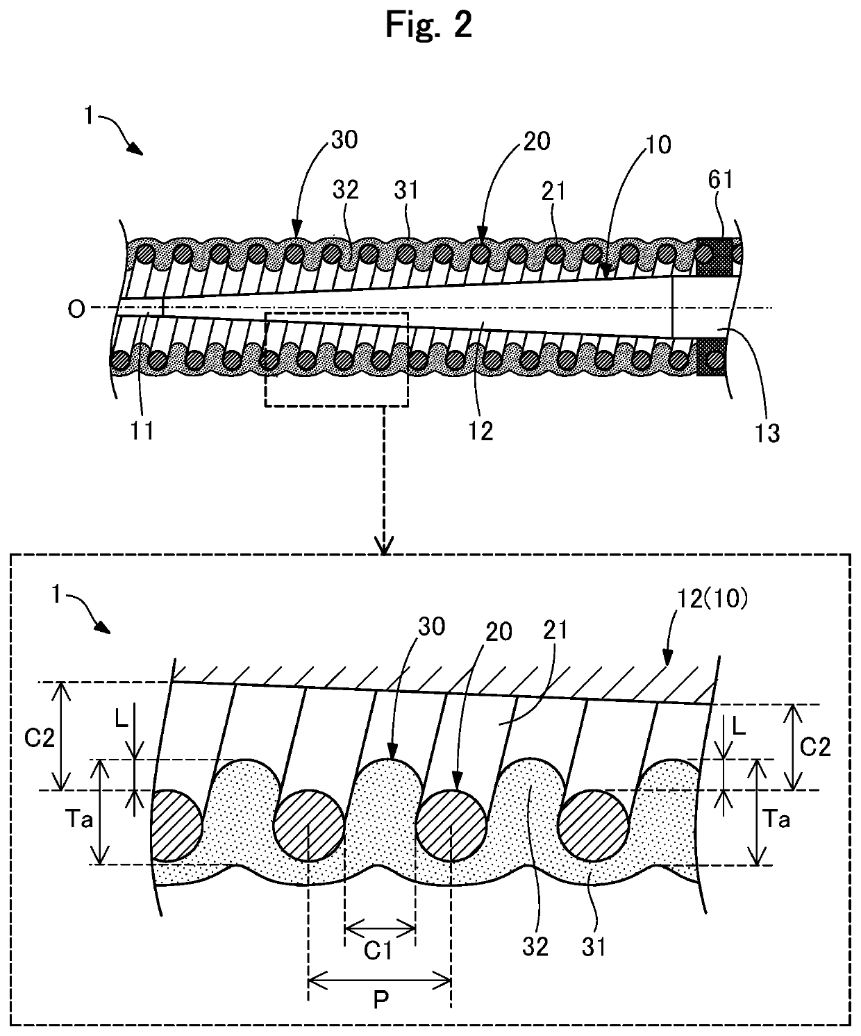
[0028]FIG. 1 is a schematic partial cross-sectional view illustrating an entire configuration of a guide wire 1 according to a first embodiment. The guide wire 1 is a medical device used when a catheter is inserted into a blood vessel or a digestive organ, and includes a core shaft 10, a coil body 20, a resin layer 30, a distal end joint part 51, a proximal end joint part 56, and an intermediate fixing part 61.

[0029]In FIG. 1, an axis passing through the center of the guide wire 1 is represented by an axis O (the dash-dot-dash line). The left side in FIG. 1 is referred to as a “distal end side” of the guide wire 1 and components, and the right side in FIG. 1 is referred to as a “proximal end side” of the guide wire 1 and components. Further, with respect to the guide wire 1 and components, an end part located on the distal end side is referred to as a “distal end part” or simply a “distal end,” and an end part located on the proximal end side is referred to as a “proximal end part” ...

second embodiment

[0053]FIG. 5 is a partial enlarged view of a guide wire 1a according to a second embodiment. In the guide wire 1a according to the second embodiment, a resin layer 30a includes protruding portions 32a. Such a protruding portion 32a is formed so that a protrusion distal end of the protruding portion 32a (a portion closest to the core shaft 10) comes into contact with the core shaft 10. The shape of a protrusion of the protruding portion 32a in the cross section illustrated in FIG. 5 is an elliptical arc shape. The protruding portion 32a may be formed by using a material and manufacturing method similar to those of the protruding portion 32 according to the first embodiment.

[0054]The protruding length L of the protruding portion 32a in the guide wire 1a is equal to the size of the void C2 between the wire 21 and the core shaft 10. Thus, the thickness Ta of the resin layer 30a can be made thicker than that in the guide wire 1 according to the first embodiment. All of the protruding por...

third embodiment

[0058]FIG. 7 is a partial enlarged view of a guide wire 1b according to a third embodiment. In the guide wire 1b according to the third embodiment, a resin layer 30b includes protruding portions 32b. A protrusion distal end of such a protruding portion 32b is joined to the core shaft 10. The shape of a protrusion of the protruding portion 32b in the cross section illustrated in FIG. 7 is a substantially rectangular shape in which a diameter of the center portion is reduced. The protruding portion 32b may be formed of a material similar to that of the protruding portion 32 according to the first embodiment. The protruding portion 32b may be formed, for example, by applying an adhesive such as an epoxy-based adhesive to the outer peripheral surface of the core shaft 10 and then applying a liquidized resin material from the outer peripheral surface of the coil body 20. When the resin material is applied, the resin material is allowed to flow from the gap C1 of the coil body 20 to reach...


PUM


Abstract

A guide wire includes a core shaft, a coil body that is a wire wound around the core shaft, and a resin layer covering at least an outer peripheral surface of the coil body. The coil body includes a spaced part in which a gap is formed between adjacent wires, and is arranged to form a void between the coil body and the core shaft. The resin layer includes a protruding portion protruding inside the void toward the core shaft through the gap between the adjacent wires in the spaced part. The protruding portion extends toward the core shaft in a direction away from an inner peripheral surface of the coil body.

Description

[0001]The present application is a Bypass Continuation of PCT / JP2018 / 017468, filed May 1, 2018, the entirety of the prior application being hereby incorporated by reference into this application.TECHNICAL FIELD[0002]The disclosed embodiments relate to a guide wire.BACKGROUND ART[0003]There is known a guide wire used for inserting a catheter into a blood vessel, a digestive organ, or the like. A guide wire made of a metal coil typically includes a core shaft using a wire material, and a coil body wound around an outer periphery of the core shaft, and a distal end of the core shaft and a distal end of the coil body are joined. In such a guide wire, a technique is known in which a resin layer is formed on the coil body for the purpose of improving slidability by smoothing the guide wire, improving the thrombus adhesion preventing property, improving operability, and the like. For example, Japanese Patent No. (JP) 5526218 and Japanese Unexamined Patent Application Publication No. (JP) 2...

Claims


Application Information

Patent Timeline
Patent Type & Authority Applications(United States)
IPC IPC(8): A61M25/09
CPCA61M25/09A61M2025/09133A61M2025/09083A61M2025/09091
Inventor KOSUGI, TOMOKITAKAHASHI, DAIKI
Owner ASAHI INTECC CO LTD
Why Eureka
Try Eureka