Center of gravity propulsion space launch vehicles

a space launch and center of gravity technology, applied in the field of rocket-propelled space launches, can solve the problems of increasing the number of personnel participating in the work, increasing the cost of each flight, increasing the cost of operation, etc., and achieve the effect of increasing the heat load during reentry

Active Publication Date: 2021-04-01
SHEERIN GEOFFREY T
View PDF0 Cites 0 Cited by
  • Summary
  • Abstract
  • Description
  • Claims
  • Application Information

AI Technical Summary

Problems solved by technology

The ground launch facilities need well-developed ground infrastructure and its associated social support (roads, power, hotels, schools, hospitals, etc.), which radically increases the number of personnel participating in the work, and, therefore, the cost of operation.
This further increases the cost of each flight.
Attempted recovery of expendable boosters on water is further complicated with the requirement to keep sea water out of the engines at the impact point.
Expensive waterproofing compartments add weight and cost to a launch vehicle and, if avoided, requires difficult precision vertical landings on water-based platforms to achieve dry recovery.
All these systems suffer from inability to land and recover the payload just seconds after launch if the flight is aborted.
Even rockets that are designed to return the first stage to a controlled landing cannot bring back the entire upper stage and payloads safely during abort at any point during the flight.
The vertical launch and landing require the handling and stacking of payload using tall cranes and high gantry systems that further complicate launch preparations and post landing servicing.
Horizontal air launched vehicles can provide some return to site and payload recovery but are by nature much smaller in payload up-mass than vertical ground launch vehicles due to size limitations of carrier aircraft and wing loading limits.
Current rocket engine technology (specific impulse limits), puts limits on the payload launched from the ground using aerodynamic lift due to the large propellant mass needed to get to orbit and the very large and heavy wings needed to lift that propellant.
This presents a problem for anyone who wants to design a space launch vehicle that takes off and lands horizontally like an aircraft.
There is an upper limit to wing loading that prevents normal aircraft design methods from being applied.
The limits of tire technology will not allow aircraft to takeoff faster than 250 knots.
Usually the designer of horizontal takeoff launch vehicles realizes this bigger, heavier wing consumes the payload fraction of the launch vehicle making it impractical as a design solution.
Then undercarriage needed to support the heavy fuel load and larger wings only adds to the payload fraction problem usually pushing it into the negative number territory.
This oversize design requires larger and heavier wings and undercarriage that consumes all or more of the payload mass to orbit.
Winged vehicles also have reentry heating issues when using a low angle of attack reentry to the earth's atmosphere.

Method used


Image

  • Center of gravity propulsion space launch vehicles
  • Center of gravity propulsion space launch vehicles
  • Center of gravity propulsion space launch vehicles

Examples


Embodiment Construction

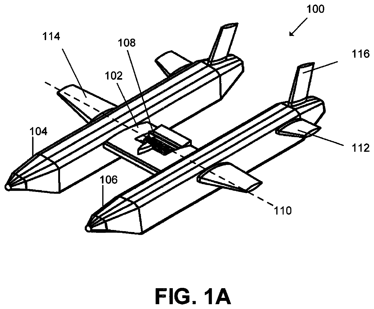
[0030]The present disclosure relates to aerospace vehicle(s) suitable for carrying substantial payload beyond the Earth's atmosphere and for return therefrom. Also disclosed is a technique of combining at least two aerospace vehicles for the horizontal launch from the surface of the earth of large payloads to earth orbital altitudes and beyond. Moreover, the present disclosure provides a logistical support method for constructing and launching vehicles from the surface of the ocean and recovery on ocean surface.

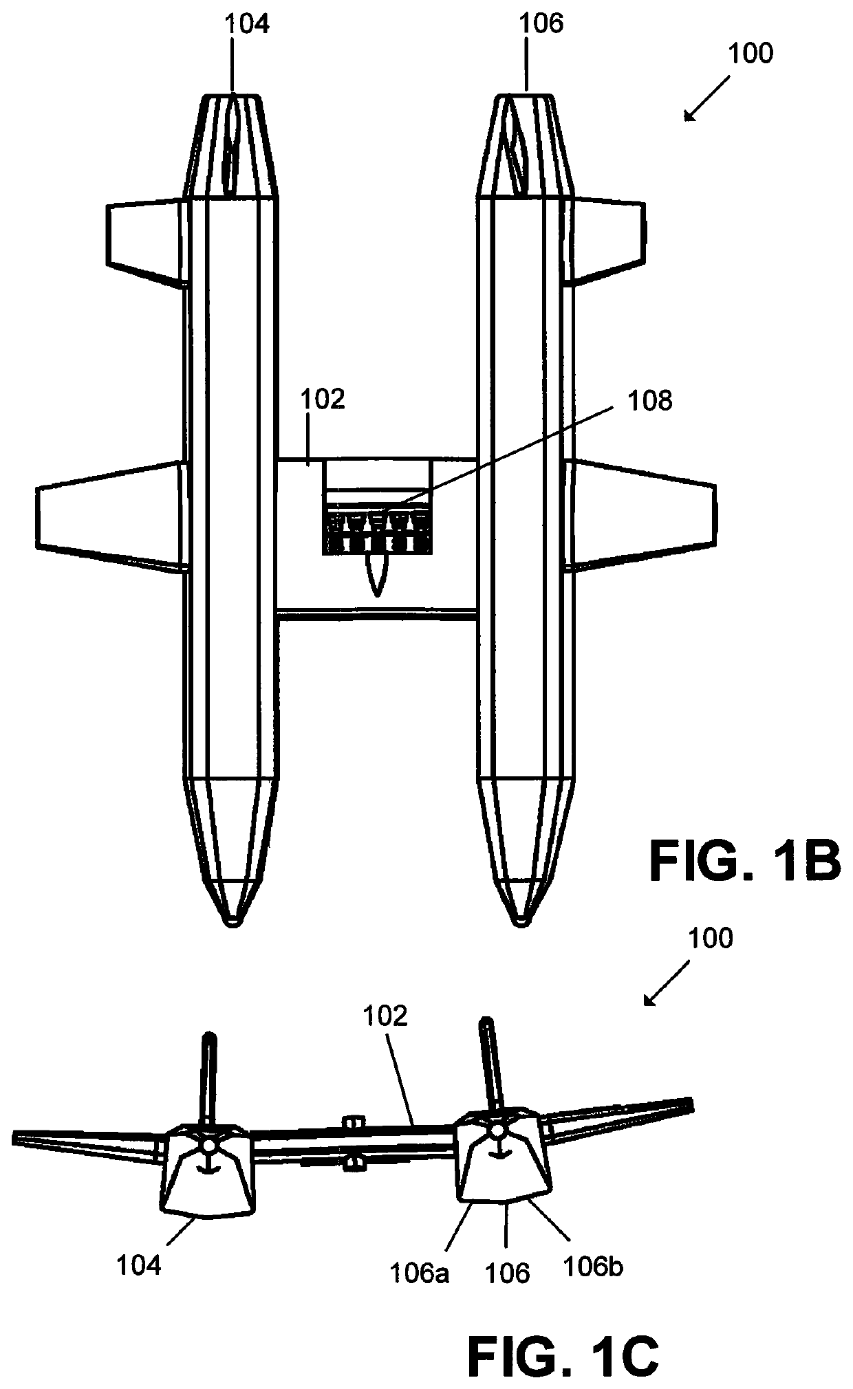
[0031]FIG. 1A, FIG. 1B and FIG. 1C illustrate a primary space launch vehicle 100 design and operational parameters of a system that can be a reusable or expendable system for horizontal takeoff and landing is described. The system can be launched from land on track or runway or from the surface of the ocean where it requires minimum launch infrastructure by eliminating pad and gantry and other conventional landing pad systems.

[0032]The vehicle 100 comprises a center wing sect...


PUM


Abstract

An aerospace vehicle that permits horizontal launch and subsequent orbital deployment of a second stage. The vehicle can be returned to Earth for subsequent re-use. Both land-based and water-based launch is disclosed. A rocket propulsion engine is located at the center of gravity of the vehicle and rotates to provide vertical and horizontal thrust.

Description

CROSS-REFERENCE TO RELATED APPLICATIONS[0001]This application claims priority to, and is a non-provisional of, U.S. Patent Application 62 / 652,369 (filed Apr. 4, 2018), the entirety of which is incorporated herein by reference.BACKGROUND OF THE INVENTION[0002]Historically, rocket propelled space launch vehicles have been, for the most part, unmanned or manned expendable ballistic devices. Except for a few air-launched rockets most space launch vehicles are launched vertically from the ground with a few vehicles using vertical decent and landing for recovery and reuse. For vertical ground launch vehicles, the rocket engines must provide thrust greater than the gross weight of the fully fueled launch vehicle. This necessitates launch vehicle designs that provide a tall thin propellant tank structure with a nose cone covering the payload on top and rocket engines on the base providing thrust and attitude control through gimbaled swivel of the engines. This launch vehicle configuration r...

Claims


Application Information

Patent Timeline
Patent Type & Authority Applications(United States)
IPC IPC(8): B64G1/14B64G1/00B64G1/40
CPCB64G1/14B64G2700/24B64G1/40B64G1/002B64C29/0075B64D27/023B64C1/00B64C2001/0045B64C39/04B64G1/005Y02T50/40B64G1/401
Inventor SHEERIN, GEOFFREY T.
Owner SHEERIN GEOFFREY T
Why Eureka
Try Eureka