
Mechanical signal processing accumulator attenuation device and method

a signal processing and accumulator technology, applied in the direction of machines/engines, process and machine control, instruments, etc., can solve the problems of flash boil, high pressure spike that can exceed the allowable pressure range of the pressure transducer, and significant duration of incorrect pressure readings, so as to improve the utilization monitoring of propellants, reduce or eliminate incorrect pressure readings, and improve the effect of pressure signal processing

Active Publication Date: 2013-05-14
UNITED LAUNCH ALLIANCE
View PDF12 Cites 3 Cited by
  • Summary
  • Abstract
  • Description
  • Claims
  • Application Information

AI Technical Summary

Benefits of technology

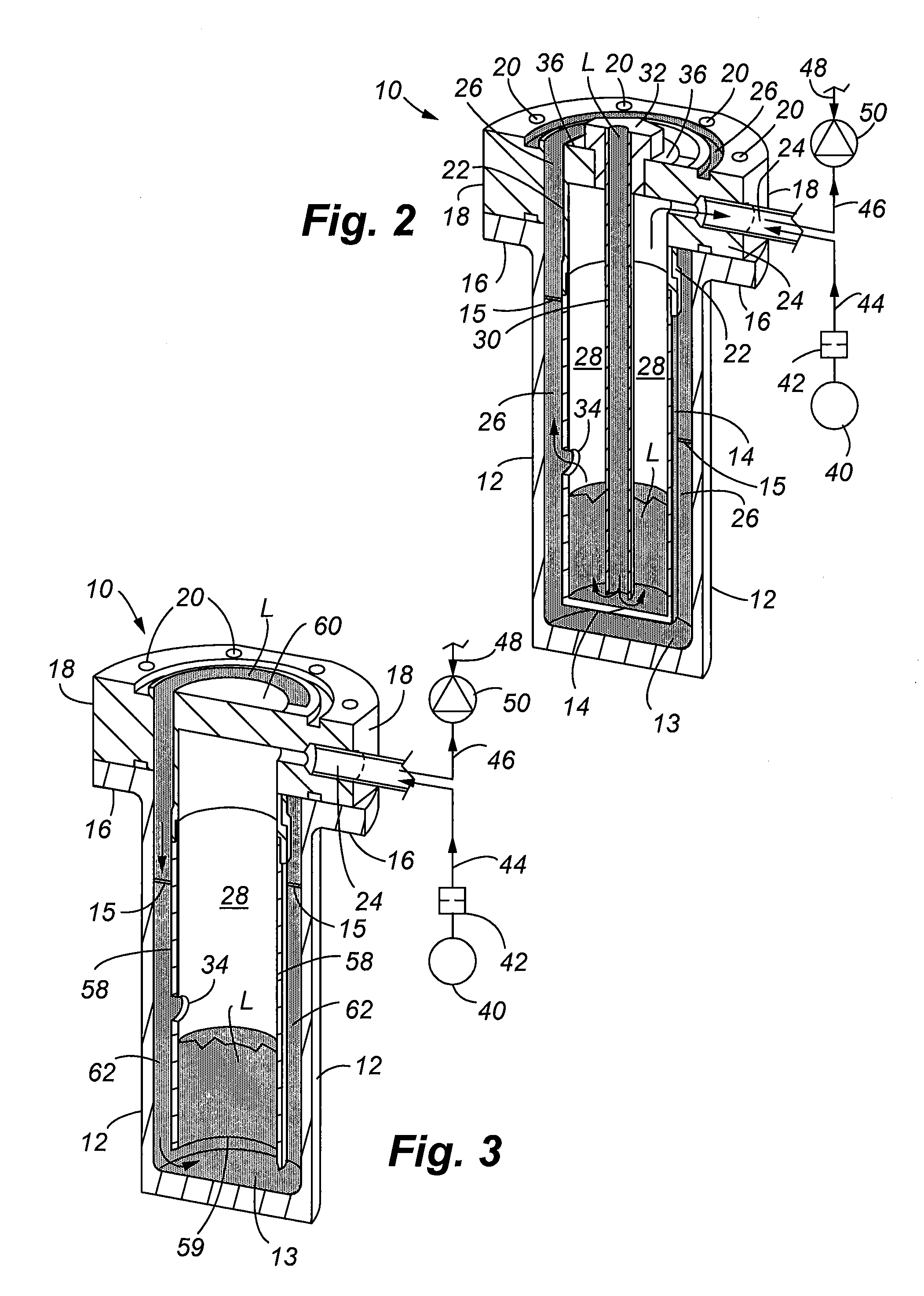
The present invention provides a device for filtering and accumulating mechanical signals in a propellant utilization system. This device reduces or eliminates incorrect pressure readings caused by vibrations or other causal pressure pulsations. It achieves this by isolating the pressure measurement location and collecting the displaced fluid within a sensing chamber. Other mechanical filtering elements can also be attached to the device to further improve pressure reading capabilities. The accumulator protects the pressure transducer from over pressure conditions in cryogenic fluid applications.

Problems solved by technology

During times in which an out of balance situation exists, the time required to regain equilibrium is not great enough to result in a significant duration of incorrect pressure readings.
When cryogenic fluid is pushed far into a warm sense line, it will flash boil and create high pressure spike that can exceed the allowable pressure range of the pressure transducer.

Method used


Image

  • Mechanical signal processing accumulator attenuation device and method
  • Mechanical signal processing accumulator attenuation device and method
  • Mechanical signal processing accumulator attenuation device and method

Examples


Embodiment Construction

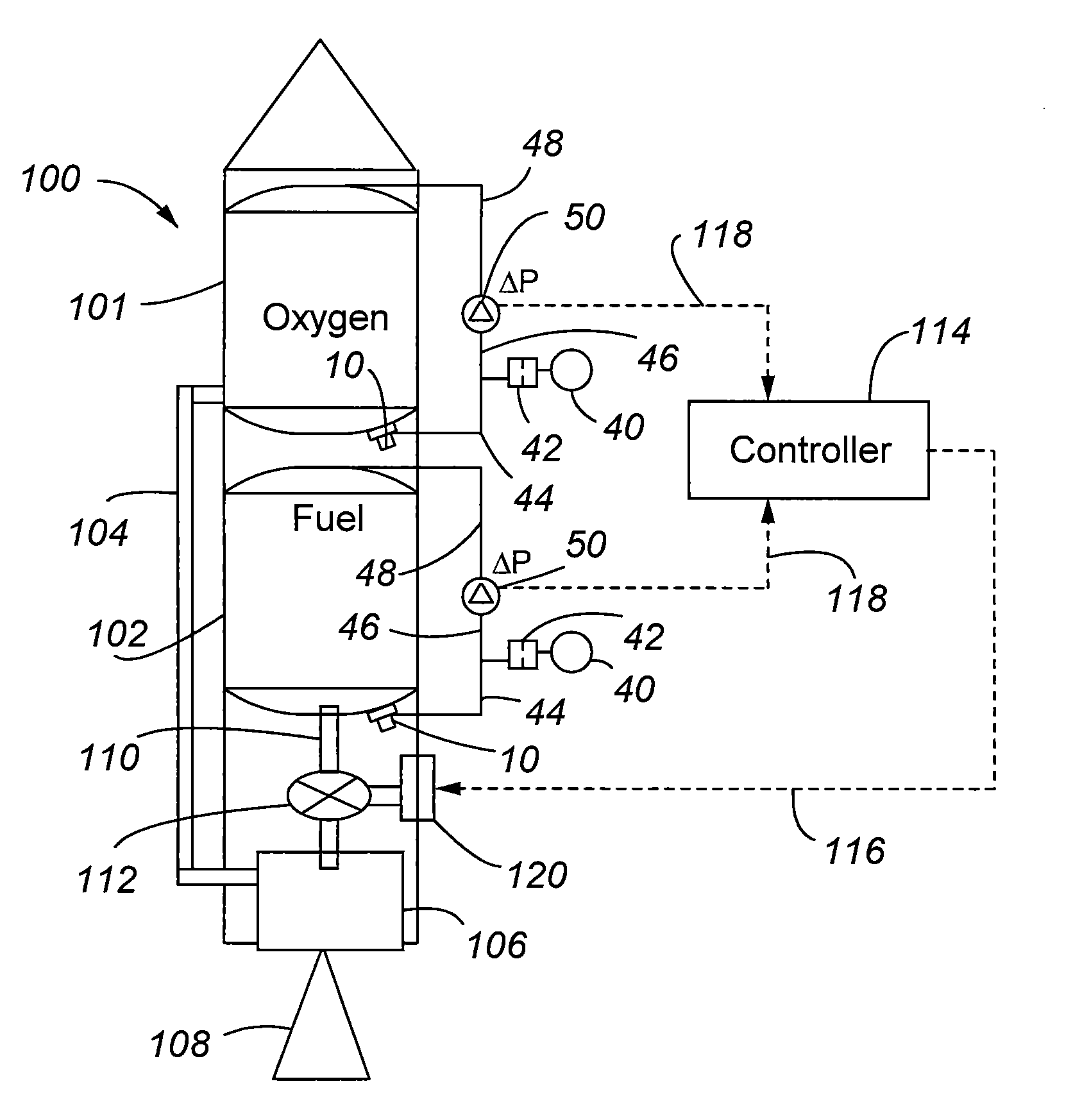
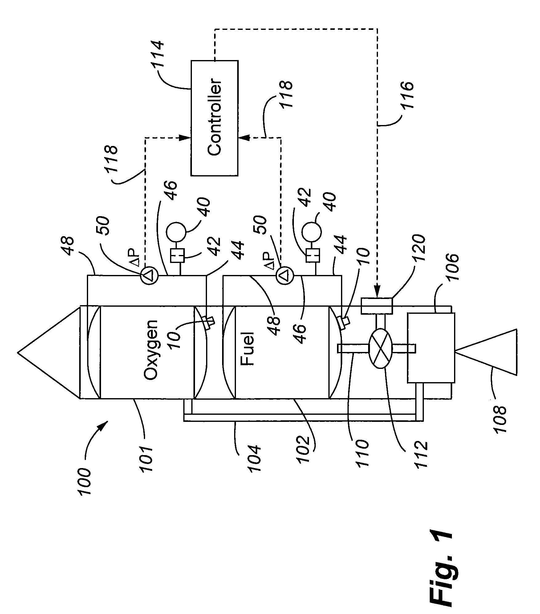
[0028]Referring to FIG. 1, a simplified schematic diagram is provided showing a launch vehicle 100 along with some of the major components of the propulsion system and propellant utilization monitoring system. More specifically, FIG. 1 illustrates the vehicle 100 having an oxidizer tank 101 that may contain a liquid propellant such as oxygen. A separate fuel tank 102 is provided that is also housed within the launch vehicle. A delivery line 104 carries the oxidizer to a combustion chamber 106 wherein the oxidizer is mixed with the fuel that enters the combustion chamber 106 through a mixing valve assembly 112. Fuel is carried from the tank 102 to the mixing valve 112 by a fuel delivery line 110. The expanded gas from the combustion is discharged through nozzle 108 which provides the motive force to move the launch vehicle. The optimum mixture ratio of fuel and oxidizer is one that results in efficient combustion and ensures all propellants are expended at the end of flight to minimi...


PUM

PropertyMeasurementUnit
cutoff frequencyaaaaaaaaaa
oscillating pressure frequencyaaaaaaaaaa
frequenciesaaaaaaaaaa

Abstract

A liquid / gas interface pressure accumulator and mechanical filter device is especially adapted for use within a propellant utilization monitoring system of a space launch vehicle. The device provides a retrofit solution for overcoming problems associated with liquid entering a pressure sensing lines and pressure noises that collectively harm the ability to accurately measure fuel and oxidizer levels. One device is attached to each fuel and oxidizer tank of the launch vehicle. Each device includes a housing and an internal sensing chamber that is used to accumulate liquid before it can enter a pressure sensing communication line connected to a pressure sensing transducer. The construction of the device also allows filtering of undesirable pressure noises due to vibration, pressure pulsations, and other vibratory events that occur during operation of the space vehicle. The device is also selectively tunable to filter out certain frequencies and frequency ranges / bands. The invention in other aspects includes methods of improving pressure sensing applications in a propellant utilization monitoring system.

Description

[0001]This invention was made with Government support under Contract No. FA8816-06-C-0002 awarded by the United States Air Force. The government has certain rights in this invention.FIELD OF THE INVENTION[0002]The present invention relates to pressure sensing systems used in combustion propulsion systems, and more particularly, to a device and method used to improve pressure sensing in a propellant utilization monitoring system of a space vehicle.BACKGROUND OF THE INVENTION[0003]Rocket powered launch vehicles provide the thrust for launching and delivering a payload from the earth into earth orbit. Payloads may include complex assemblies such as satellites. Launch vehicles typically include one or more rocket engines configured to activate at different times or stages as the launch vehicle travels from the earth into orbit. A rocket engine in a launch vehicle may incorporate a solid or liquid propellant contained in a propellant tank, a combustion chamber, and a nozzle for directing...

Claims


Application Information

Patent Timeline
Patent Type & Authority Patents(United States)
IPC IPC(8): G01L7/00G01F23/00B64G1/40
CPCF02K9/54F02K9/58F05D2270/301F05D2220/80
Inventor ROGERS, JEFFREY J.BRENNAN, PAUL R.
Owner UNITED LAUNCH ALLIANCE
Learn More