Liquid hydrogen supercooling degree acquisition system for space launching site
A technology for obtaining system and subcooling degree, applied in heat recovery systems, refrigerators, refrigeration components, etc., can solve the problem of urgent demand for subcooled hydrogen, and achieve the effects of avoiding the risk of ice blockage, easy engineering implementation, and high operating efficiency.
- Summary
- Abstract
- Description
- Claims
- Application Information
AI Technical Summary
Problems solved by technology
Method used
Image
Examples
Embodiment 1
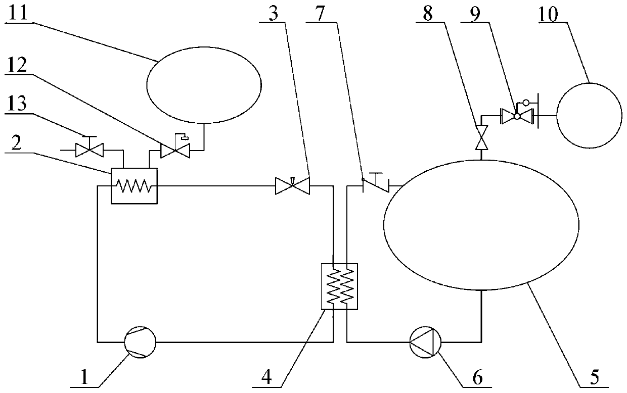
[0038] Example 1, such as figure 1 As shown, a liquid hydrogen subcooling acquisition system for an aerospace launch site includes a liquid hydrogen storage tank 5, and the top pressurization port of the liquid hydrogen storage tank 5 passes through a back pressure regulating valve 8, a pressure relief valve 9 and a high-pressure helium cylinder 10 Outlet connection; the outlet at the bottom of the liquid hydrogen storage tank 5 is connected to the inlet of the circulation pump 6, the outlet of the circulation pump 6 is connected to the liquid hydrogen side inlet of the helium-hydrogen heat exchanger 4, and the liquid hydrogen side outlet of the helium-hydrogen heat exchanger 4 is connected to the return check The inlet of the valve 7 and the outlet of the return check valve 7 are connected to the return port on the top of the liquid hydrogen storage tank 5;
[0039]The helium side outlet of the helium-hydrogen heat exchanger 4 is connected to the inlet of the cold helium comp...
Embodiment 2
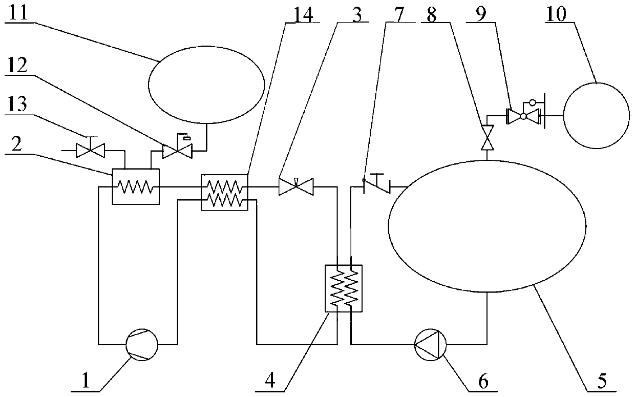
[0049] Example 2, such as figure 2 As shown, on the basis of Embodiment 1, a recooler 14 is added, the first helium inlet of the recooler 14 is connected to the helium side outlet of the helium-hydrogen heat exchanger 4, and the first helium of the recooler 14 The gas outlet is connected to the inlet of the cold helium compressor 1, the outlet of the cold helium compressor 1 is connected to the helium side inlet of the liquid hydrogen bath heat exchanger 2, and the helium side outlet of the liquid hydrogen bath heat exchanger 2 is connected to the recooler 14 The second helium inlet and the second helium outlet of the recooler 14 are connected to the inlet of the throttle valve 3, and the outlet of the throttle valve 3 is connected to the helium side inlet of the helium-hydrogen heat exchanger 4.
[0050] The helium pre-cooled by the liquid hydrogen bath heat exchanger 2 is further pre-cooled to a lower temperature by the recooler 14, thereby reducing the temperature of the h...
Embodiment 3
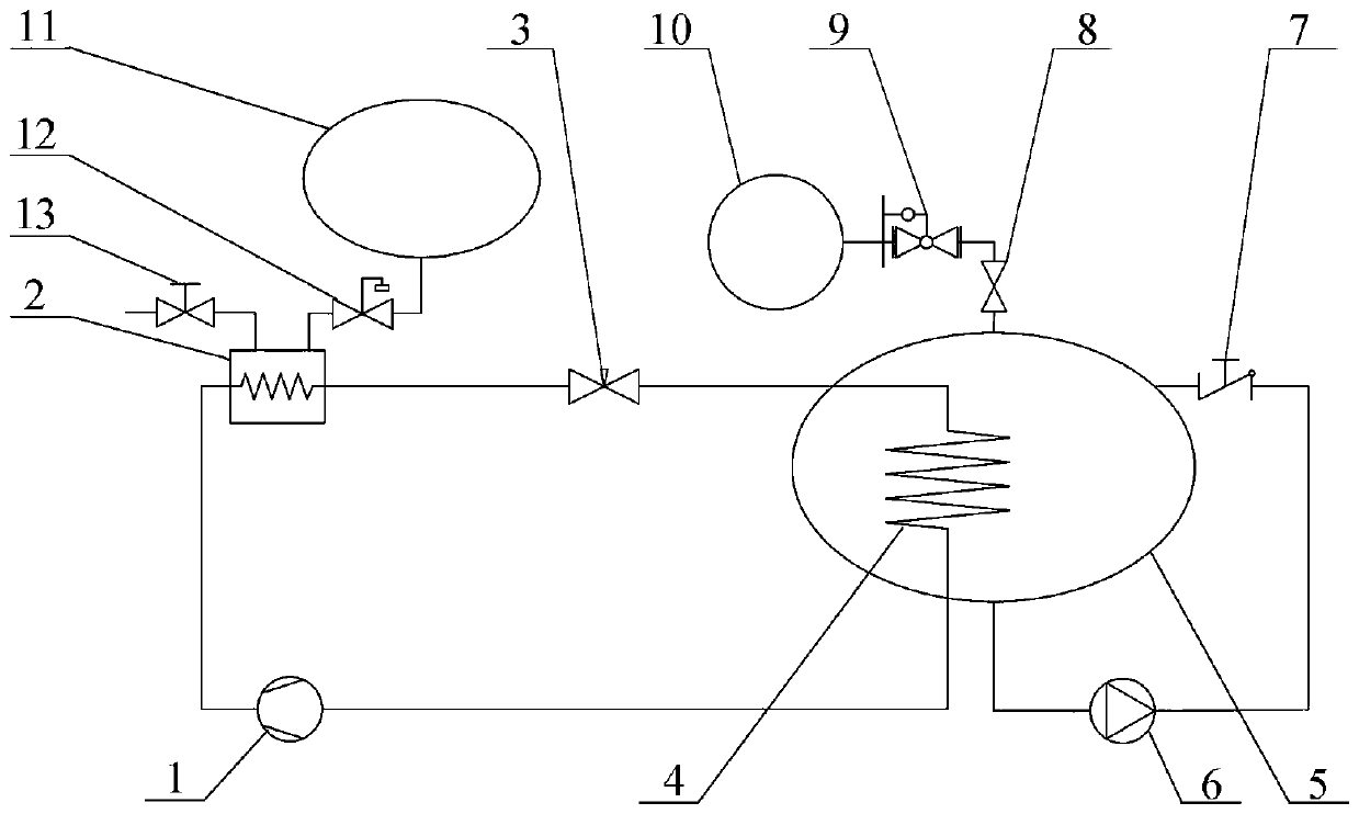
[0051] Embodiment 3, with reference to image 3 , on the basis of Example 1, the helium-hydrogen heat exchanger 4 is placed inside the liquid hydrogen storage tank 5, and the cold helium directly supercools the liquid hydrogen in the liquid hydrogen storage tank 5; the outlet of the throttle valve 3 is connected to the helium- The helium side inlet of the hydrogen heat exchanger 4, the helium side outlet of the helium-hydrogen heat exchanger 4 is connected to the inlet of the cold helium compressor 1; the bottom outlet of the liquid hydrogen storage tank 5 is connected to the inlet of the circulation pump 6, and the outlet of the circulation pump 6 is connected to the return stop The inlet of the return valve 7 and the outlet of the return check valve 7 are connected to the return port on the top of the liquid hydrogen storage tank 5 . The function of the circulation pump branch is to achieve sufficient stirring of the liquid hydrogen in the liquid hydrogen storage tank 5 to a...
PUM
 Abstract
Description
Claims
Application Information
 - R&D
- Intellectual Property
- Life Sciences
- Materials
- Tech Scout
- Unparalleled Data Quality
- Higher Quality Content
- 60% Fewer Hallucinations
Browse by: Latest US Patents, China's latest patents, Technical Efficacy Thesaurus, Application Domain, Technology Topic, Popular Technical Reports.
© 2025 PatSnap. All rights reserved.Legal|Privacy policy|Modern Slavery Act Transparency Statement|Sitemap|About US| Contact US: help@patsnap.com


