A system for obtaining liquid hydrogen subcooling degree at space launch site

A technology for obtaining system and supercooling degree, which is applied in heat recovery systems, refrigerators, refrigeration components, etc., can solve problems such as the urgent demand for supercooled hydrogen, and achieve the effects of avoiding the risk of ice blockage, improving performance, and being easy to implement in engineering

Active Publication Date: 2021-07-27
XI AN JIAOTONG UNIV
View PDF5 Cites 0 Cited by
  • Summary
  • Abstract
  • Description
  • Claims
  • Application Information

AI Technical Summary

Problems solved by technology

[0006] So far, the aerospace field has achieved supercooling of propellants such as liquid oxygen, liquid methane, and kerosene, but has not yet carried out engineering-level supercooling operations for liquid hydrogen. Future aerospace exploration has an urgent need for supercooled hydrogen

Method used


Image

  • A system for obtaining liquid hydrogen subcooling degree at space launch site
  • A system for obtaining liquid hydrogen subcooling degree at space launch site
  • A system for obtaining liquid hydrogen subcooling degree at space launch site

Examples


Embodiment 1

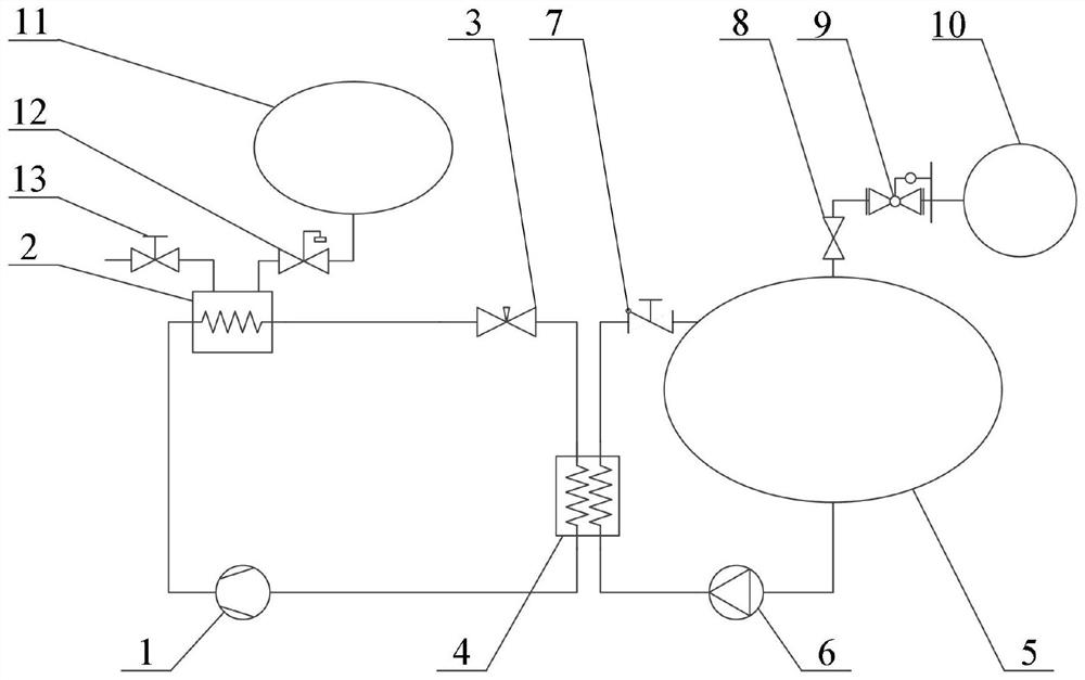
[0038] Example 1, such as figure 1 As shown, a liquid hydrogen subcooling acquisition system for an aerospace launch site includes a liquid hydrogen storage tank 5, and the top pressurization port of the liquid hydrogen storage tank 5 passes through a back pressure regulating valve 8, a pressure relief valve 9 and a high-pressure helium cylinder 10 Outlet connection; the outlet at the bottom of the liquid hydrogen storage tank 5 is connected to the inlet of the circulation pump 6, the outlet of the circulation pump 6 is connected to the liquid hydrogen side inlet of the helium-hydrogen heat exchanger 4, and the liquid hydrogen side outlet of the helium-hydrogen heat exchanger 4 is connected to the backflow check The inlet of the valve 7 and the outlet of the return check valve 7 are connected to the return port on the top of the liquid hydrogen storage tank 5;

[0039]The helium side outlet of the helium-hydrogen heat exchanger 4 is connected to the inlet of the cold helium co...

Embodiment 2

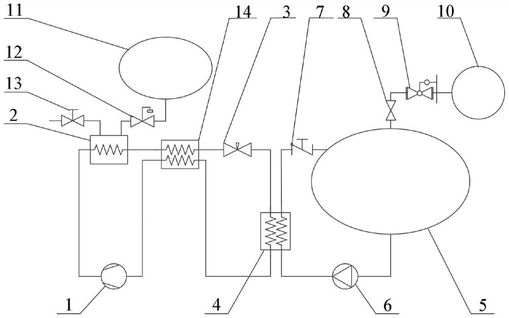
[0049] Example 2, such as figure 2 As shown, on the basis of Embodiment 1, a recooler 14 is added, the first helium inlet of the recooler 14 is connected to the helium side outlet of the helium-hydrogen heat exchanger 4, and the first helium of the recooler 14 The gas outlet is connected to the inlet of the cold helium compressor 1, the outlet of the cold helium compressor 1 is connected to the helium side inlet of the liquid hydrogen bath heat exchanger 2, and the helium side outlet of the liquid hydrogen bath heat exchanger 2 is connected to the recooler 14 The second helium inlet and the second helium outlet of the recooler 14 are connected to the inlet of the throttle valve 3, and the outlet of the throttle valve 3 is connected to the helium side inlet of the helium-hydrogen heat exchanger 4.

[0050] The helium pre-cooled by the liquid hydrogen bath heat exchanger 2 is further pre-cooled to a lower temperature by the recooler 14, thereby reducing the temperature of the h...

Embodiment 3

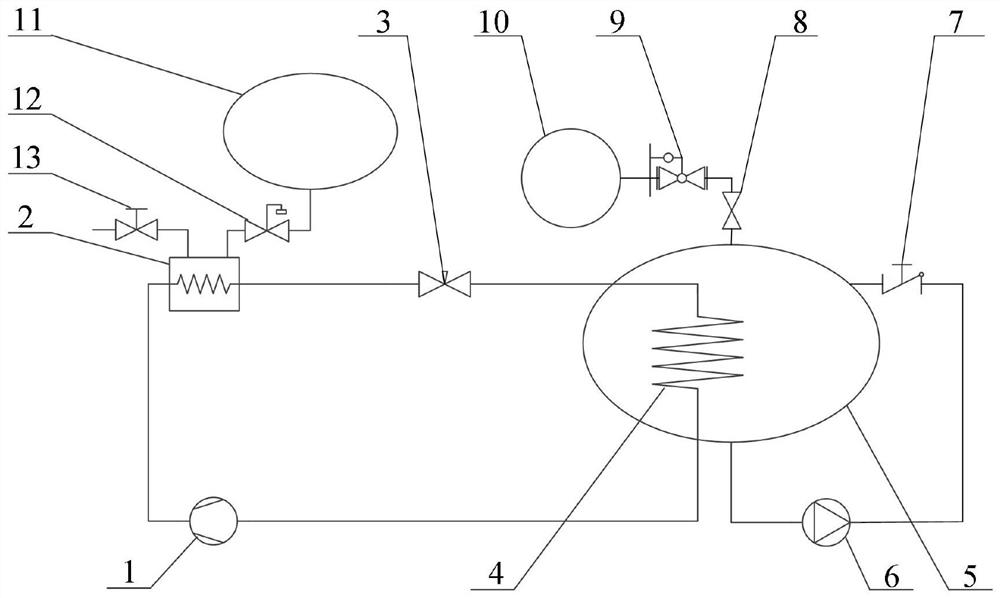
[0051] Embodiment 3, with reference to image 3 , on the basis of Example 1, the helium-hydrogen heat exchanger 4 is placed inside the liquid hydrogen storage tank 5, and the cold helium directly supercools the liquid hydrogen in the liquid hydrogen storage tank 5; the outlet of the throttle valve 3 is connected to the helium- The helium side inlet of the hydrogen heat exchanger 4, the helium side outlet of the helium-hydrogen heat exchanger 4 is connected to the inlet of the cold helium compressor 1; the bottom outlet of the liquid hydrogen storage tank 5 is connected to the inlet of the circulation pump 6, and the outlet of the circulation pump 6 is connected to the return stop The inlet of the return valve 7 and the outlet of the return check valve 7 are connected to the return port on the top of the liquid hydrogen storage tank 5 . The function of the circulation pump branch is to achieve sufficient stirring of the liquid hydrogen in the liquid hydrogen storage tank 5 to a...


PUM


Abstract

A liquid hydrogen subcooling degree acquisition system for an aerospace launch site, comprising a liquid hydrogen storage tank, the top pressure booster port of the liquid hydrogen storage tank is connected to the outlet of a high-pressure helium cylinder through a valve; the bottom outlet of the liquid hydrogen storage tank is connected to helium- The liquid hydrogen side inlet of the hydrogen heat exchanger and the liquid hydrogen side outlet of the helium-hydrogen heat exchanger are connected to the return port at the top of the liquid hydrogen storage tank through a return check valve; the helium gas side outlet of the helium-hydrogen heat exchanger is compressed by cold helium The machine is connected to the helium side inlet of the liquid hydrogen bath heat exchanger, and the helium side outlet of the liquid hydrogen bath heat exchanger is connected to the helium side inlet of the helium-hydrogen heat exchanger through a throttle valve; the liquid hydrogen bath heat exchanger The liquid hydrogen inlet is connected to the bottom outlet of the liquid hydrogen storage tank through a float regulating valve, and the hydrogen outlet of the liquid hydrogen bath heat exchanger is evacuated through a hydrogen drain valve; the present invention utilizes a large number of liquid hydrogen cold sources in the launch site to implement pre-cooling , Combined with the cold helium compressor, it can realize the large-scale on-site preparation of liquid hydrogen with large subcooling degree; the equipment investment and transformation cost are low, and it is easy to realize engineering.

Description

technical field [0001] The invention relates to the technical field of preparation of densified low-temperature fuel at an aerospace launch site, in particular to a system for obtaining the subcooling degree of liquid hydrogen at an aerospace launch site. Background technique [0002] Liquid hydrogen / liquid oxygen is currently a group of propellant combinations with the highest specific impulse. Compared with normal temperature propellants, its specific impulse is 30% to 40%. Therefore, the application of this propellant to the upper stage of the launch vehicle can significantly improve the rocket launch ability. [0003] Liquid hydrogen for aerospace is usually at the saturation temperature, that is, 20K, and its density at normal pressure is about 71.3kg / m 3 . If the liquid hydrogen is supercooled, it will help increase the density of liquid hydrogen, reduce the volume of the storage tank, and improve the rocket's carrying capacity. When liquid hydrogen is supercooled t...

Claims


Application Information

Patent Timeline
Patent Type & Authority Patents(China)
IPC IPC(8): F25B9/12F25B9/06F25B49/02F28D21/00F28F27/00
CPCF25B9/06F25B9/12F25B49/02F28D21/00F28F27/00Y02B30/56
Inventor 王磊上官石刘柏文厉彦忠谢福寿马原
Owner XI AN JIAOTONG UNIV
Why Eureka
Try Eureka