

Analysis Method and Analysis Apparatus
an analysis apparatus and analysis method technology, applied in the direction of material analysis using wave/particle radiation, material separator tube details, instruments, etc., can solve the problems of taking time and the time-consuming to obtain the spectral map
- Summary
- Abstract
- Description
- Claims
- Application Information
AI Technical Summary
Benefits of technology
Problems solved by technology
Method used
Image

Examples
first embodiment
1. First Embodiment
1. 1. Auger Electron Microscope
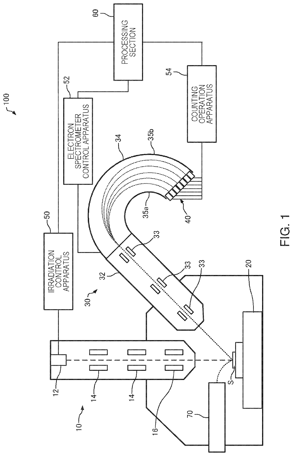
[0092]First, an Auger electron microscope used in an analysis method according to a first embodiment will be described with reference to the drawings. FIG. 1 is a diagram schematically showing an Auger electron microscope 100.
[0093]The Auger electron microscope 100 is an apparatus for performing analysis of a specimen by Auger electron spectroscopy. In the Auger electron microscope 100, an electron emitted from a specimen S by irradiating the specimen S with a primary probe such as an electron beam is analyzed and detected by an electron spectrometer 30, and elemental analysis is thereby performed.
[0094]As illustrated in FIG. 1, the Auger electron microscope 100 includes an electron beam irradiation apparatus 10, a specimen stage 20, the electron spectrometer 30, an irradiation control apparatus 50, an electron spectrometer control apparatus 52, a counting operation apparatus 54, a processing section 60, and a secondary electron dete...
second embodiment
2. Second Embodiment
2. 1. Auger Electron Microscope
[0237]The configuration of the Auger electron microscope used in an analysis method according to a second embodiment is the same as that of the Auger electron microscope 100 illustrated in FIG. 1 described above, and hence the description thereof will be omitted. The processing section 60 performs processing of correcting drift of the analysis field described below.
2. 2. Analysis Method
[0238]FIG. 25 is a flowchart illustrating an example of the analysis method according to the second embodiment. As illustrated in FIG. 25, the analysis method according to the second embodiment includes the step S15 of correcting the drift of the analysis field. In the following description, a description will be given of points different from those of the example of the analysis method according to the first embodiment described above, and the description of points similar to those of the example thereof will be omitted.
[0239]In the Auger electron mi...
third embodiment
3. Third Embodiment
3. 1. Auger Electron Microscope
[0255]The configuration of the Auger electron microscope used in an analysis method according to a third embodiment is the same as that of the Auger electron microscope 100 illustrated in FIG. 1 described above, and hence the description thereof will be omitted.
3. 2. Analysis Method
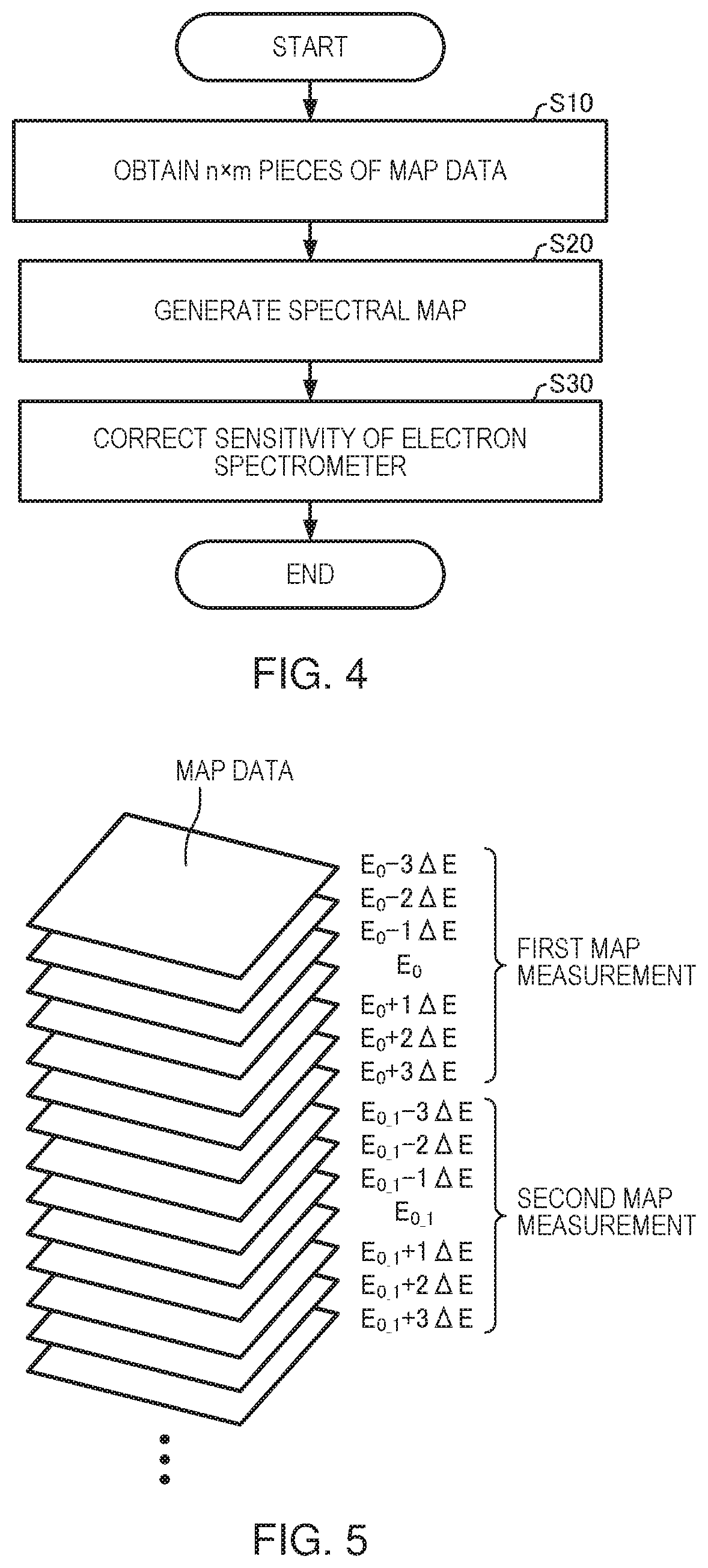
[0256]Next, a description will be given of the analysis method according to the third embodiment. In the analysis method according to the third embodiment, the step S10 of obtaining n×m pieces of map data illustrated in FIG. 4 and the step S30 of correcting the sensitivity of the electron spectrometer 30 illustrated in FIG. 4 are different from those of the analysis method according to the first embodiment. In the following description, a description will be given of points different from those of the example of the analysis method according to the first embodiment described above, and the description of points similar to those of the example thereof will ...
PUM
 Abstract
Description
Claims
Application Information