Determination of the rotor temperature of a permanent magnet synchronous machine

Active Publication Date: 2021-04-01
AUDI AG
View PDF7 Cites 0 Cited by
  • Summary
  • Abstract
  • Description
  • Claims
  • Application Information

AI Technical Summary

Benefits of technology

The object of this invention is to provide a better method and device for figuring out the temperature of the rotor in an electric vehicle with a permanent magnet synchronous machine. This new technique solves a problem where the starting value was not very precise, and it allows for a more accurate calculation of the rotor temperature. This helps to protect the components of the machine and to model the rotor temperature accurately. The patent text outlines the advantages of this invention and the benefits it can provide for electric vehicles.

Problems solved by technology

Rotor temperature of a permanent magnet synchronous machine cannot be determined directly using existing technologies, since no temperature sensor can be installed in the rotor.
The model can only estimate the rotor temperature; an exact determination is not possible.
In addition, a starting value problem arises if the vehicle is switched off.

Method used


Image

  • Determination of the rotor temperature of a permanent magnet synchronous machine

Examples


Embodiment Construction

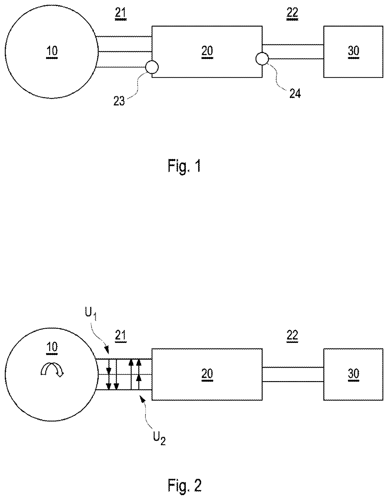
[0033]FIG. 1 schematically shows a drive train of an electric vehicle configured to carry out methods according to embodiments of the invention. The drive train comprises a permanent magnet synchronous machine (PSM) 10, a power electronics system 20 supplying the PSM 10 with electrical energy and a high-voltage (HV) battery 30. An AC side 21 of the power electronics system 20 has three phases connected to the PSM 10. A DC side 22 of the power electronics system 20 is connected to the HV battery 30.

[0034]The power electronics system 20 comprises a current sensor 23 in one of the three phases to the PSM 10 on the AC side 21 and a voltage sensor 24 on the DC side 22. The measured values of these two sensors of the power electronics can be used in determining the rotor temperature.

[0035]If the power electronics system 20 is operated in a current regulation mode and is regulated such that the alternating voltage on the AC side 21 is zero, the alternating voltage on the AC side 21 can be ...


PUM


Abstract

Methods and apparatuses for determining a rotor temperature of a permanent magnet synchronous machine (PSM) of an electrically driven vehicle are described.

Description

BACKGROUNDTechnical Field[0001]Embodiments of the present invention relate to a method and an apparatus for determining rotor temperature of a permanent magnet synchronous machine (PSM) of an electrically-driven vehicle.Description of the Related Art[0002]Rotor temperature of a permanent magnet synchronous machine cannot be determined directly using existing technologies, since no temperature sensor can be installed in the rotor. However, the rotor temperature is crucial for component protection of the electrical machine.[0003]In existing technologies, rotor temperature is deduced by a temperature model stored in a converter on the basis of a load profile and of measured data from sensors located nearby. The model can only estimate the rotor temperature; an exact determination is not possible. In addition, a starting value problem arises if the vehicle is switched off. The rotor temperature is unknown after restarting. The control unit has no information as to how long the vehicle h...

Claims


Application Information

Patent Timeline
IPC IPC(8): H02P29/66
CPCH02P29/662H02P21/14H02P6/00Y02T10/64
Inventor KARL, BERNHARDADAM, MARTINHEBER, SEBASTIANHONKOMP, FRANZ
Owner AUDI AG
Why Eureka
Try Eureka