

Roll-bonded laminate
- Summary
- Abstract
- Description
- Claims
- Application Information
AI Technical Summary
Benefits of technology
Problems solved by technology
Method used
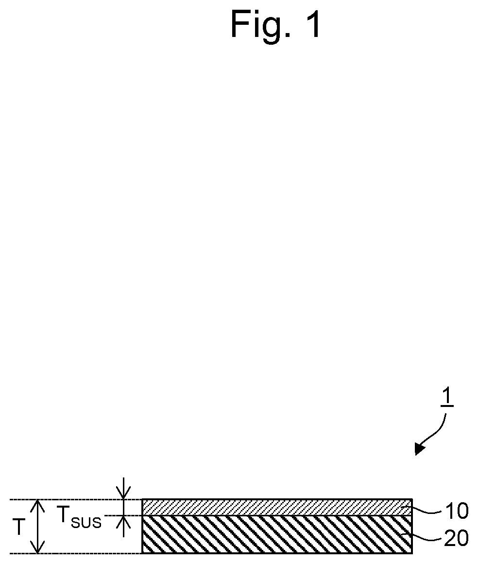
Image

Examples
example 1
[0074]The roll-bonded laminate was produced via surface-activated bonding. SUS304 BA (thickness 0.05 mm) was used as a stainless steel plate, and A5052 aluminum alloy (thickness 0.8 mm) was used as an aluminum plate. SUS304 and A5052 were subjected to sputter etching. SUS304 was subjected to sputter etching at 0.3 Pa and a plasma output of 700 W for 12 minutes, and A5052 was subjected to sputter etching at 0.3 Pa and a plasma output of 700 W for 12 minutes. After the sputter-etching treatment, SUS304 was roll-bonded to A5052 with a roll diameter of 100 mm to 250 mm at room temperature, a line pressure load of 0.5 tf / cm to 5.0 tf / cm, and a reduction ratio of the stainless steel layer of 0% to 5%. Thus, the roll-bonded laminate of SUS304 and A5052 was obtained. This roll-bonded laminate was subjected to batch thermal treatment at 300° C. for 1 hour.
example 8
[0084]SUS304 BA (thickness 0.25 mm) was used as a stainless steel plate, and A5052 aluminum alloy (thickness 0.8 mm) was used as an aluminum plate. SUS304 and A5052 were subjected to sputter etching. SUS304 was subjected to sputter etching at 0.1 Pa, a plasma output of 4800 W, and a line velocity of 4 m / min. A5052 was subjected to sputter etching at 0.1 Pa, a plasma output of 6400 W, and a line velocity of 4 m / min. After the sputter-etching treatment, SUS304 was roll-bonded to A5052 at room temperature and a line pressure load of 3.0 tf / cm to 6.0 tf / cm. Thus, the roll-bonded laminate of SUS304 and A5052 was obtained. This roll-bonded laminate was subjected to batch thermal treatment at 300° C. for 8 hours.
examples 9 to 12
[0085]The roll-bonded laminates of Examples 9 to 12 were produced in the same manner as in Example 8, except that steel type, conditions, and thickness of the original stainless steel plate and / or aluminum type and thickness of the original aluminum plate were changed and the pressure at the time of bonding was changed to a given level.
[0086]In Example 9, SUS304 1 / 2H (thickness 0.25 mm) was used as a stainless steel plate, and A5052 aluminum alloy (thickness 0.8 mm) was used as an aluminum plate.
[0087]In Example 10, SUS316L BA (thickness 0.2 mm) was used as a stainless steel plate, and A5052 aluminum alloy (thickness 0.8 mm) was used as an aluminum plate.
[0088]In Example 11, SUS304 BA (thickness 0.25 mm) was used as a stainless steel plate, and A1050 aluminum (thickness 0.8 mm) was used as an aluminum plate.
[0089]In Example 12, SUS316L BA (thickness 0.25 mm) was used as a stainless steel plate, and A1050 aluminum (thickness 0.8 mm) was used as an aluminum plate.
PUM
| Property | Measurement | Unit |
|---|---|---|
| Length | aaaaa | aaaaa |
| Length | aaaaa | aaaaa |
| Temperature | aaaaa | aaaaa |
Abstract
Description
Claims
Application Information