
First patent magnetic propulsion method

a technology of magnetic propulsion and magnetic field, applied in the direction of electric generator control, dynamo-electric machines, control systems, etc., can solve the problems of any system using rotating magnets, reducing the output power of a load,

Inactive Publication Date: 2021-04-08
MARTINEZ JOHN R +1
View PDF0 Cites 0 Cited by
  • Summary
  • Abstract
  • Description
  • Claims
  • Application Information

AI Technical Summary

Benefits of technology

The technical effects of this patent text involve an electrical power generator that uses stationary and rotating magnets to generate power. It also describes a method of using a rotating non-contact iron enclosure and a mechanical cam timing to control the switching of power. Additionally, a method for neutralizing / un-neutralizing multiple static magnets to repel a free spinning magnetic wheel at specific intervals is also described. The generator is designed to provide a more efficient and controlled generation of electrical power.

Problems solved by technology

The opposing magnets cause a drag in the system which will lower the available output power delivered to a load.
This problem can occur in any system using rotating magnets to generate power.

Method used


Image

  • First patent magnetic propulsion method
  • First patent magnetic propulsion method
  • First patent magnetic propulsion method

Examples


Embodiment Construction

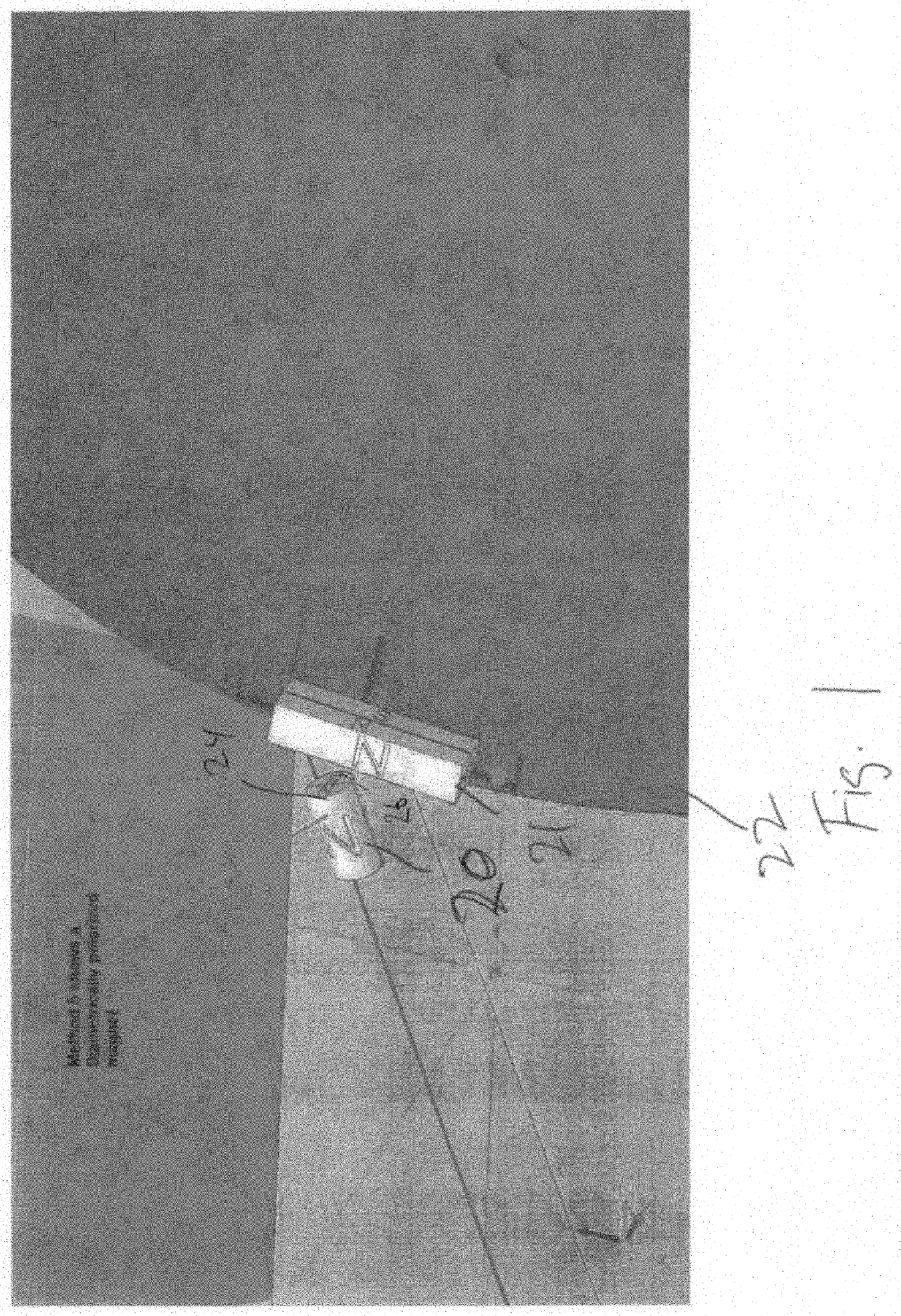
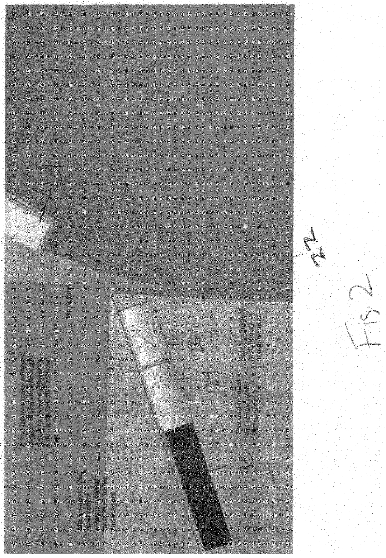
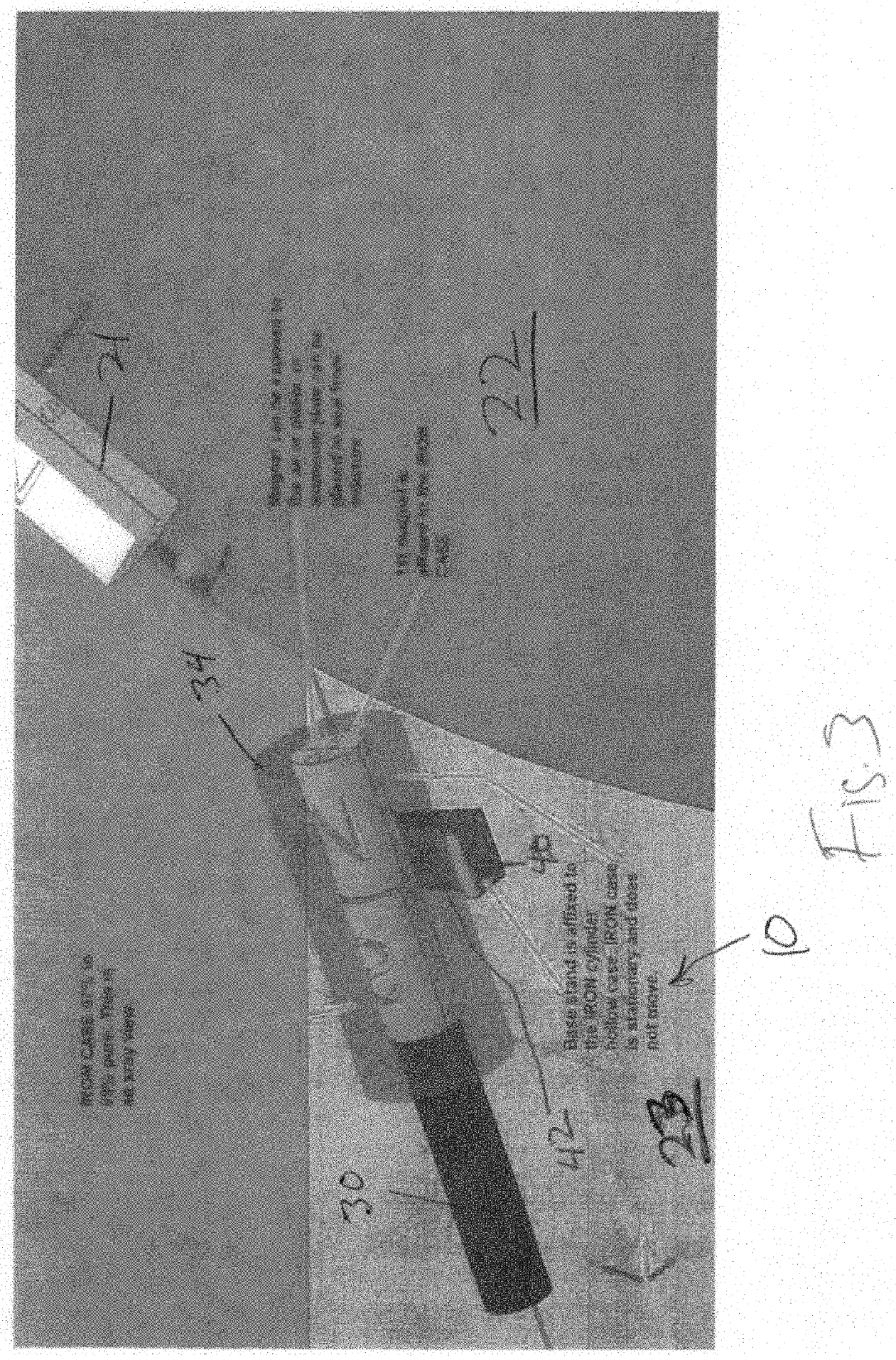
[0014]The present invention is directed to a method of neutralizing a stationary magnet which stationary magnet is used to propel a series of magnets positioned on a spinning wheel or other rotating mechanism. U.S. Pat. No. 4,751,486 discloses a magnetic rotation apparatus having first and second rotors, which are supported and connected such that they can rotate in opposite directions in a cooperating manner. The first and second rotors include same number of permanent magnets arranged on their circumferential portions at regular intervals. One of the permanent magnets of one rotor is replaced with an electromagnet, which is connected to a drive circuit. The drive circuit includes a power source for supplying an electric current to the coil of the electromagnet. Each permanent magnet has one magnetic polarity located radially outward from the rotors and the other magnetic polarity located radially inward toward the rotors. The radially outward polarity of each permanent magnet is i...


PUM


Abstract

A rotating magnet electrical power generator. The apparatus may be used with any electrical generator that uses a rotating magnet assembly. A key aspect of the invention is the neutralization of one of the pair of rotating magnets, the neutralization occurring at predetermined intervals. Neutralization is effected by blocking the magnetic field of the stationary magnet using a cam operated metal enclosure or metal plates. The metal field blocker, which is made from mostly iron, is dynamically positioned in accordance with the relative positions of the stationary and rotating magnets. The iron enclosure (or plates) may be connected to a brushless servo or brushless stepper motor to precisely control the switching without a mechanical cam timing. In an alternative embodiment, the magnets are neutralized by stacking a pair of cylindrical magnets end to end, enclosing the magnets at least partially in a field blocking enclosure, and rotating the magnets relative to each other to effect neutralization.

Description

FIELD OF THE INVENTION[0001]The present invention relates to power generation. More particularly, the invention discloses a device that generates electricity from a rotating magnet assembly.BACKGROUND OF THE INVENTION[0002]Power generating devices using rotating magnet assemblies are well known in the art. Both generators and alternators run on the basic principle of producing electricity from an AC magnetic field. A type of power generator similar to the inventive device is shown in world patent number WO1990010337 issued to Troy Reed. According to the Reed patent “This is a magnetic motor having a crankshaft mounted between two stationary disk-like magnetic holders. Preferably eight permanent magnets are positioned equally distance about the periphery of each disk. Fixed on the end of each shaft is a rotatable magnetic support wheel which has a similar number of magnets equally spaced about its periphery. The magnets on one such wheel are 22½° out of alignment with the magnets on ...

Claims


Application Information

Patent Timeline
Patent Type & Authority Applications(United States)
IPC IPC(8): H02P9/02
CPCH02P9/02H02K53/00H02P9/00
Inventor MARTINEZ, JOHN R.RIDDLE, JEFFREY J.
Owner MARTINEZ JOHN R
Learn More