Powered air purifying respirator device

a respirator and air purification technology, applied in the field of respirator devices, can solve the problems of increasing the weight of the unit, the bulk of the papr unit, and the general size and weight of the uni

Pending Publication Date: 2021-04-22
RPB SAFETY
View PDF8 Cites 0 Cited by
  • Summary
  • Abstract
  • Description
  • Claims
  • Application Information

AI Technical Summary

Benefits of technology

[0006]The present invention provides a powered air purifying respirator device for easy replacement of the filter module and cleaning of the unit. In addition, the present invention allows for replacement of the filter module without separate handling of a spark arrestor in the respirator device. Further, the present invention allows improved air flow across the filter module. The present invention further provides a door assembly provides for limiting contaminants from entering the interior of the respirator device.
[0007]The construction of the respirator device is light-weight, allowing for ease of use regardless of the stature of the user. The present invention provides a PAPR unit that is lighter in weight and more compact than other known units. Several features combine to make this possible. It is also easier to clean and maintain than known units.
[0008]The volute chamber is unique. The center line of the volute chamber is on an angle relative to the impeller. This enables the space inside the housing to be better utilized, without complicating the geometry of the housing. It also simplifies the balancing of the impeller, as the bottom face on the impeller can remain parallel to reference geometry of the housing. The design has been engineered to achieve a similar functional performance to a volute with a chamber that is not offset.

Problems solved by technology

One of the problems with known PAPR units is their bulk.
They are typically fairly large and heavy.
To extend the period of time the unit can be used, conventional units use large batteries and this increases the weight of the unit.
Also, to provide the needed air flow, conventional units use bigger fans which result in the need for bigger housings.
Another problem with conventional PAPR units is the placement of the battery on the outside of the unit.
This exposes the battery to environmental contaminants so that, in addition to the unit itself, the battery is required to be cleaned as well.
The battery is also exposed to potential damage from impact with other items in the work area.
Conventional units are also difficult to assemble and clean.
This also makes them difficult to clean since contaminants can get into narrow gaps and pocket-shaped geometry, as well as under screws.
The contaminants then build-up, making it difficult to disassemble the unit.
For example, if the battery is covered by a battery door, the external portions of the battery door, as well as the battery itself, are exposed to environmental contaminants due to the design of battery door.
The battery being placed outside the PAPR unit also exposes it to potential damage from impact with other items in the work area.

Method used


Image

  • Powered air purifying respirator device
  • Powered air purifying respirator device
  • Powered air purifying respirator device

Examples


Embodiment Construction

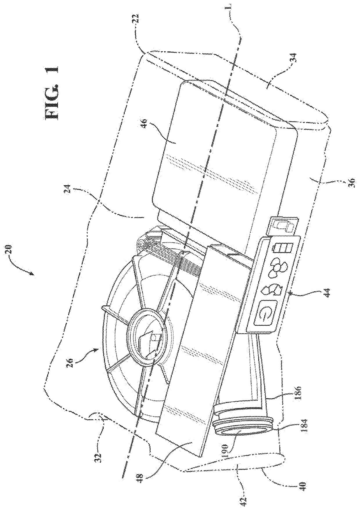
[0028]Referring to the figures, wherein like numerals indicate corresponding parts throughout the several views, a respirator device 20 constructed in accordance with one embodiment of the present invention is generally shown in FIG. 1. Typically, a respirator device 20 is secured to a user and supplies clean air to the user. FIG. 9 illustrates an example of the respirator 20 of the present invention operatively connected to headgear, such as a helmet 21, through a hose 23.

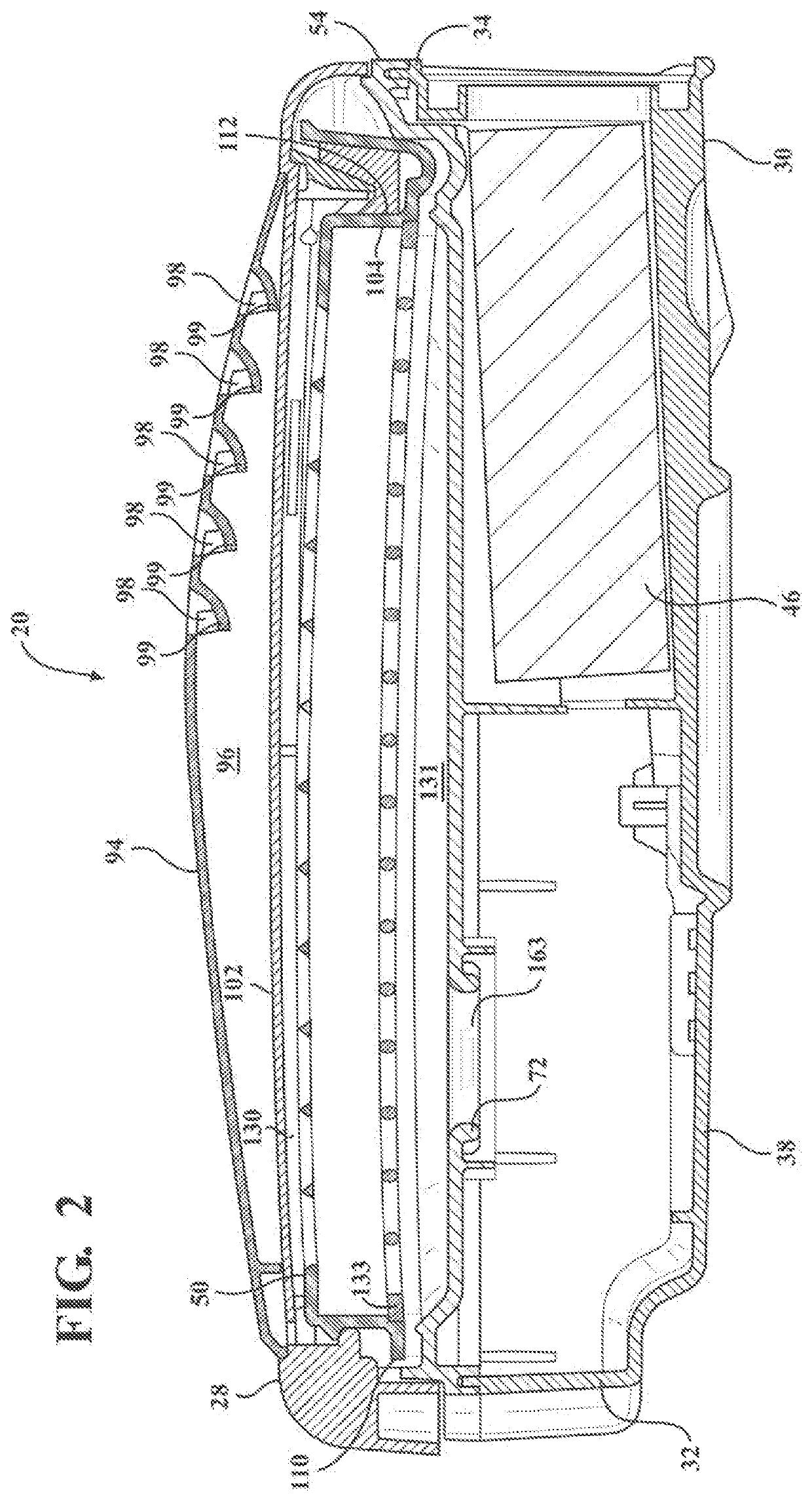
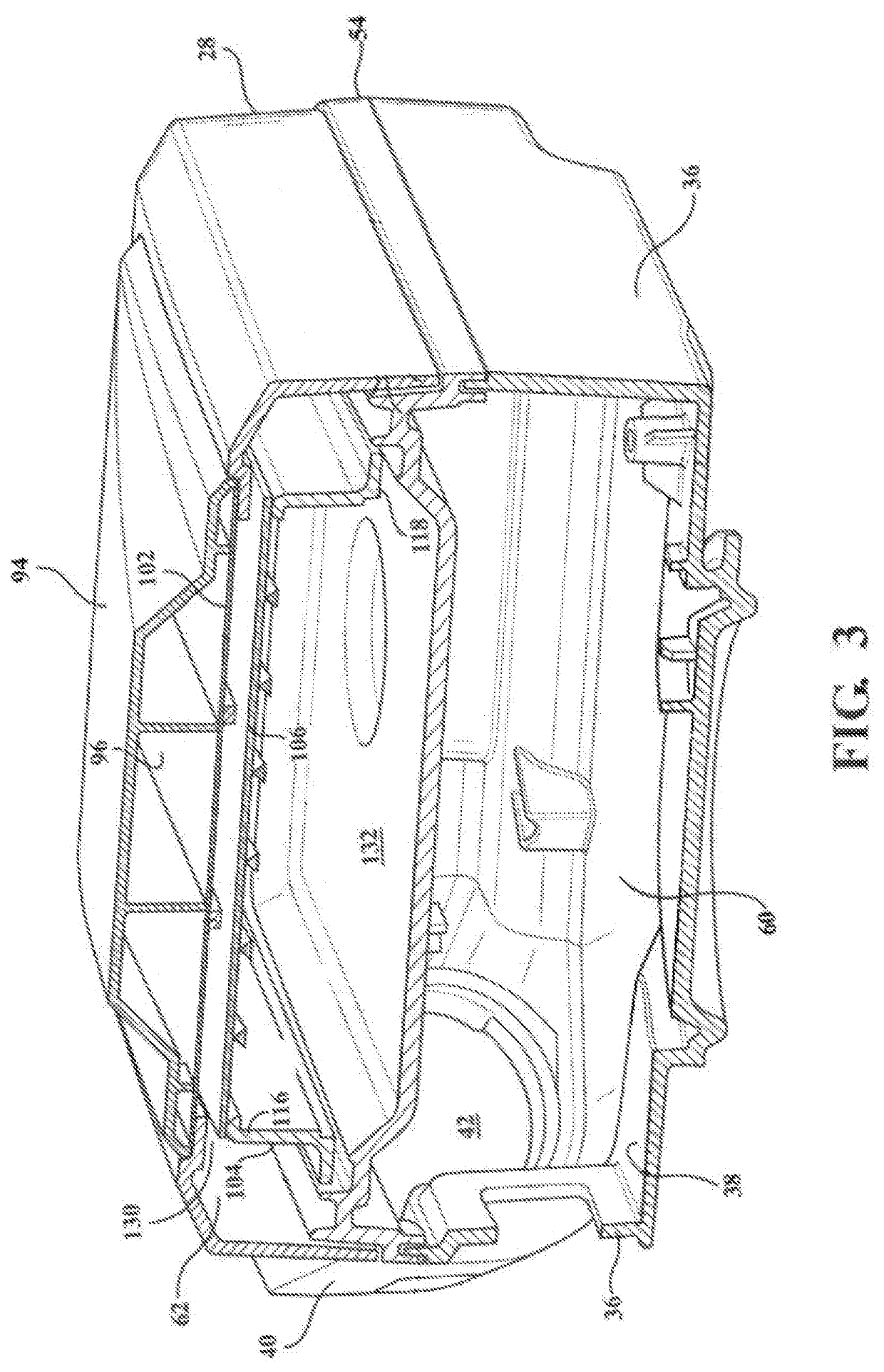
[0029]As best illustrated in FIGS. 1-3, the respirator device 20 includes an enclosure 22 extending between a first end and a second end spaced from one another along a longitudinal axis L. The enclosure has a generally rectangular shape and defines an interior 24 for containing a blower system 26 to draw air into the device 20, pressurize the air, and provide filtered air to the user. The enclosure 22 is arranged to be a generally water-proof and dust-proof interior 24 in operation. The enclosure 22 includes an u...


PUM


Abstract

A powered air purifying respirator (PAPR) device comprises an enclosure extending along a longitudinal axis between a first end of the enclosure and a second end of the enclosure. The enclosure defines an air inlet in fluid communication with environmental air. A filter module is disposed in the enclosure in fluid communication with the air inlet for filtering the environmental air to produce clean air. A blower system is disposed in the enclosure in fluid communication with the filter module for pressurizing the clean air. The enclosure includes an upper housing for receiving the filter module. A plate extends between the first end and the second end defining an air outlet in fluid communication with the filter module and the blower system. The air inlet is disposed adjacent the second end and the air outlet is disposed adjacent the first end.

Description

CROSS-REFERENCE TO RELATED APPLICATIONS[0001]This application claims the benefit of U.S. Provisional application patent Ser. No. 62 / 916,729, filed on Oct. 17, 2019, the entire disclosure of which is hereby incorporated herein by reference in its entirety.BACKGROUND OF THE INVENTION1. Field of the Invention[0002]The present invention generally relates to respirator devices, and more particularly to a powered air purifying respirator (PAPR).2. Description of the Prior Art[0003]Powered air purifying respirator equipment is generally known in the art for providing breathable air to a user's breathing zone in a hazardous environment. The powered air purifying respirator (PAPR) is typically worn by the user as a backpack or attached to a belt which is worn around the user's waist. The PAPR is connected by a hose to, for example, a helmet or face shield worn by the user. The PAPR has a motor and a fan that pulls air through a filter and then supplies filtered air to the user inside the hel...

Claims


Application Information

Patent Timeline
Patent Type & Authority Applications(United States)
IPC IPC(8): A62B18/00A62B23/02A42B3/28
CPCA62B18/006A42B3/286A62B23/02
Inventor HAMILL, WILLIAM C.WILLIAMS, EDWARD S. M.BARTNIK-THUMM, JULIATE AIKA, JAMES A.GERRARD, ALAN J.KELLY, SAMUEL M.
Owner RPB SAFETY
Why Eureka
Try Eureka