Capacitive stealth composite structure

a composite structure and capacitive technology, applied in the field of capacitive stealth composite structure, can solve the problems of affecting the speed of the aircraft, changing the aerodynamics, reducing the absorption effect, and affecting the stealth, and achieve the effect of reflection loss

Inactive Publication Date: 2021-04-22
NATIONAL TSING HUA UNIVERSITY
View PDF0 Cites 1 Cited by
  • Summary
  • Abstract
  • Description
  • Claims
  • Application Information

AI Technical Summary

Benefits of technology

[0038]To verify the effects of the invention, experiments are provided below, but the invention is not limited to the experiments below.
[0040]The analysis was performed using the Arch Method of the United States Naval Research Laboratory (NRL), as shown in FIG. 4.
[0041]In FIG. 4, an object to be tested 400 is placed on an aluminum plate 402, and electromagnetic waves 408 of different frequencies are emitted on the surface of the object to be tested 400 using a movable transmitting end 404 and a receiving end 406 (the dotted line represents 404 and 406 moving to different positions), and the electromagnetic waves 408 reflected back from the object to be tested 400 are received. According to the electromagnetic wave energy comparison between the transmitting end 404 and the receiving end 406, reflection loss may be obtained.

Problems solved by technology

However, the former requires changing the shape of the aircraft, which changes the aerodynamics and affects the speed of the aircraft; the latter produces conical edge scattering at the edge of the material and the intersection between the materials and reduces the absorption effect.
Due to the inherent impedance of the material itself having the property of absorbing electromagnetic waves not matching the inherent impedance of the air, the electromagnetic waves emitted by the radar are often reflected before entering the material for absorption, thus affecting stealth.

Method used


Image

  • Capacitive stealth composite structure
  • Capacitive stealth composite structure
  • Capacitive stealth composite structure

Examples


experimental example 1

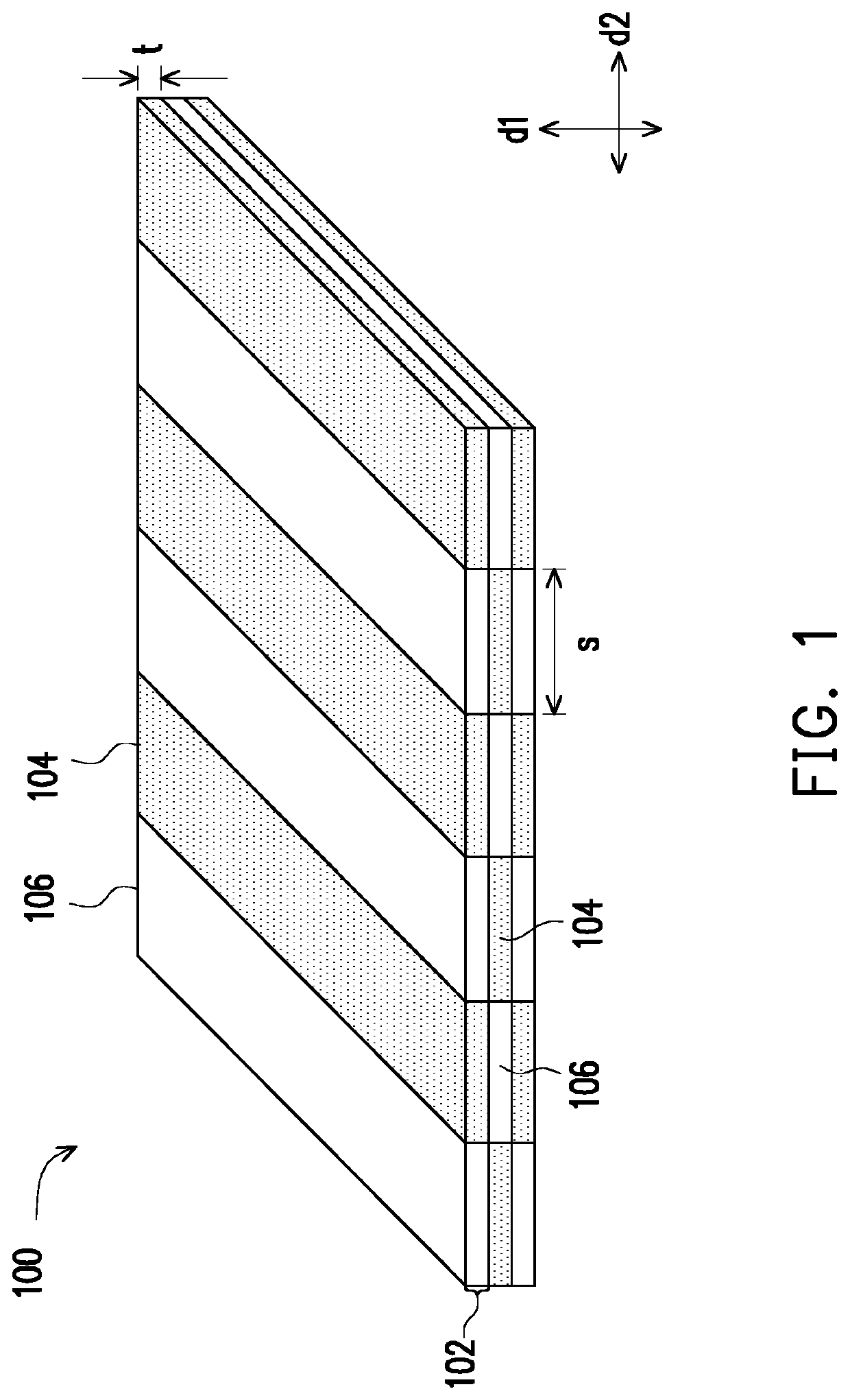
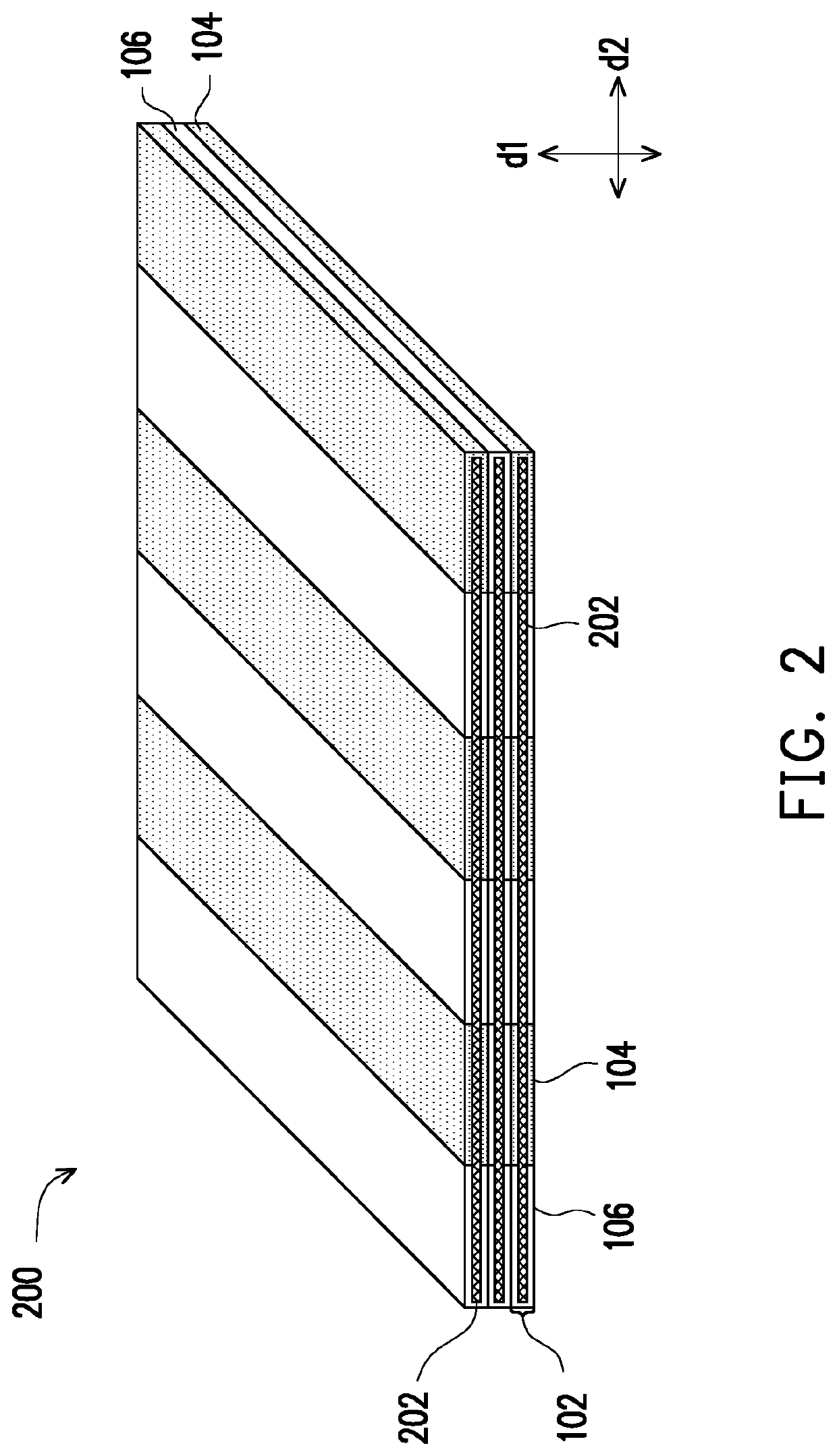
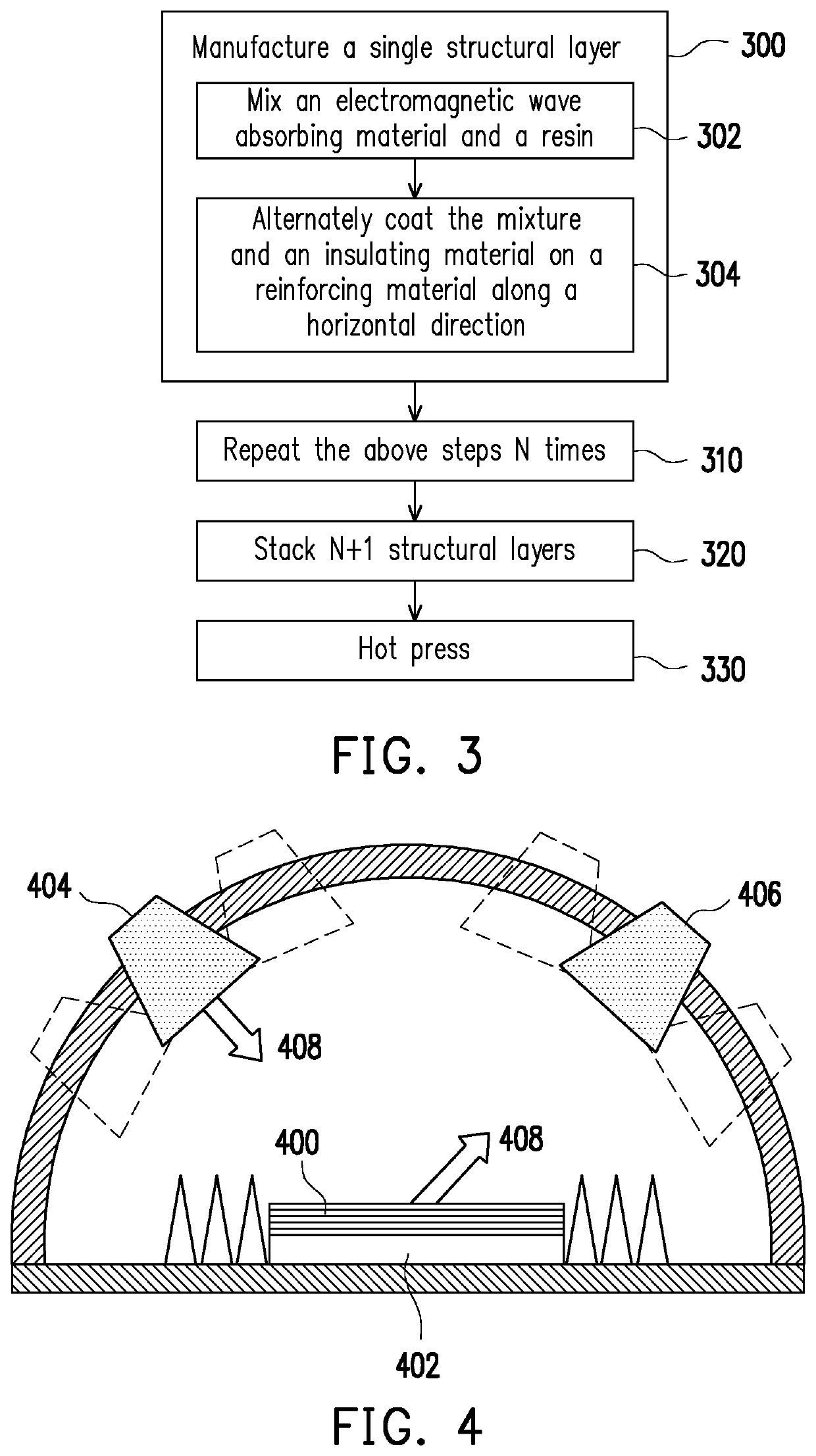
[0042]A capacitive stealth composite structure was manufactured according to the steps of FIG. 3, wherein the reinforcing material was glass fiber cloth, the insulating material was epoxy resin, and the electromagnetic wave absorbing material contained 2 phr of carbon nanotubes, 200 phr of carbonyl iron, and an epoxy resin, wherein phr is the number of parts added per 100 parts by mass of the resin.

[0043]First, the electromagnetic wave absorbing material was stirred by a triaxial roller for 1 hour and vacuum pumped, and the mixed electromagnetic wave absorbing material and the insulating material were alternately coated on the glass fiber cloth in a horizontal direction by pouring, wherein the width of the electromagnetic wave absorbing patterns was about 3 cm to 10 cm and the spacing of the electromagnetic wave absorbing patterns was about 3 cm to 10 cm, and the width of the electromagnetic wave absorbing patterns was substantially equal to the spacing between the electromagnetic w...

experimental example 2

[0048]Similar to the preparation method of Experimental example 1, but the spacing between the electromagnetic wave absorbing patterns was changed to 10 cm. Then, electromagnetic wave absorption analysis was performed, and the results are shown in FIG. 6.

experimental example 3

[0049]Similar to the preparation method of Experimental example 1, but the spacing between the electromagnetic wave absorbing patterns was changed to 3 cm. Then, electromagnetic wave absorption analysis was performed, and the results are shown in FIG. 6.

[0050]As may be seen from FIG. 5, as the spacing of the electromagnetic wave absorbing patterns was changed, the band in which the capacitive stealth composite structure had the electromagnetic wave absorption pattern was also changed, so that the electromagnetic wave absorbing pattern spacing in the capacitive stealth composite structure may be adjusted according to the application surface.

[0051]For example, if based on a reflection loss of −10 dB, the shielding band of Experimental example 1 was 8.49 GHz to 12.38 GHz, which is applicable to the electromagnetic wave shielding of radars, satellite communication, and speed guns. The shielding band of Experimental example 2 was 13.4 GHz to 15.3 GHz, which is applicable to the electroma...


PUM

PropertyMeasurementUnit
thicknessaaaaaaaaaa
widthaaaaaaaaaa
thicknessaaaaaaaaaa

Abstract

A capacitive stealth composite structure includes a plurality of structural layers stacked in a thickness direction, and the number of layers of the structural layers is three or more, wherein each of the structural layers consists of a plurality of electromagnetic wave absorbing patterns and a plurality of insulation patterns alternately arranged in a horizontal direction. The electromagnetic wave absorbing patterns in each of the structural layers are aligned with the insulation patterns of an adjacent structural layer, and the insulation patterns in each of the structural layers are aligned with the electromagnetic wave absorbing patterns of an adjacent structural layer.

Description

CROSS-REFERENCE TO RELATED APPLICATION[0001]This application claims the priority benefit of Taiwan application serial no. 108137535, filed on Oct. 17, 2019. The entirety of the above-mentioned patent application is hereby incorporated by reference herein and made a part of this specification.BACKGROUND OF THE INVENTIONField of the Invention[0002]The invention relates to stealth technology, and more particularly to a capacitive stealth composite structure.Description of Related Art[0003]The so-called stealth technology mainly uses two methods to reduce the radar cross section (RCS) reflected from the target to the radar. The first common method is to reflect an electromagnetic wave emitted by a radar to a direction in which signals may not be intercepted by a radar receiving station by changing the geometric shape. In the other method, a material having the property of absorbing electromagnetic waves is added to the outer casing of a fighter or a warship to achieve stealth by changin...

Claims


Application Information

Patent Timeline
Patent Type & Authority Applications(United States)
IPC IPC(8): H01Q17/00B32B5/02B32B5/26
CPCH01Q17/005B32B5/02B32B5/26B32B2307/212B32B2255/02B32B2255/26B32B2262/101B32B2250/20B32B19/02B32B19/04B32B19/046B32B19/06B32B29/005B32B29/02B32B2255/06B32B2255/20B32B2255/28B32B2260/021B32B2260/046B32B2262/0269B32B2262/067B32B2262/10B32B2262/106B32B2307/204B32B2307/206H01Q17/00B32B2260/023B32B2264/101B32B2264/1055B32B2264/1056H01Q17/004
Inventor FU, HAO-WEITSAI, HSIN-JUNGHSU, WEN-KUANG
Owner NATIONAL TSING HUA UNIVERSITY
Why Eureka
Try Eureka