
Monitoring in distributed computing system

Pending Publication Date: 2021-05-06
MASTERCARD INT INC
View PDF0 Cites 0 Cited by
  • Summary
  • Abstract
  • Description
  • Claims
  • Application Information

AI Technical Summary

Benefits of technology

The patent text describes a method that uses peer-to-peer communication between monitoring processes to balance practical processing requirements and security requirements. This approach allows for faster information exchanges with less monitoring information needed to be shared.

Problems solved by technology

There are multiple technical challenges with requiring a centralized system to provide services to a very large number of clients, particularly when these are widely geographically distributed.
Decentralisation may itself be problematic, particularly if it is necessary for services to be provided in such a way that provision of the service has consequences beyond the server providing the service and the client receiving it.
If, for example, other clients (or other system nodes) need to refer back to the service providing node to check on whether, or how, the service has been provided, or if it is necessary for a central system to have knowledge of how the service has been provided or of expected operation of the distributed server node, then new bottlenecks may appear in place of the former bottleneck at the central server, the overall quantity of messaging in the system may increase, and network latency can become a serious issue.
This is particular serious when the service relates to security (so it is necessary to be confident that it has been securely performed across the whole system) and when it relates to provision of a service over a short time frame.
Performing activities securely in a distributed environment of this kind is challenging, because there is potential for malicious parties to exploit the possibility that an action may be performed in one of several places in a number of ways.

Method used


Image

  • Monitoring in distributed computing system
  • Monitoring in distributed computing system
  • Monitoring in distributed computing system

Examples


Embodiment Construction

[0030]Specific embodiments of the disclosure are now described, by way of example, with reference to the accompanying drawings, of which:

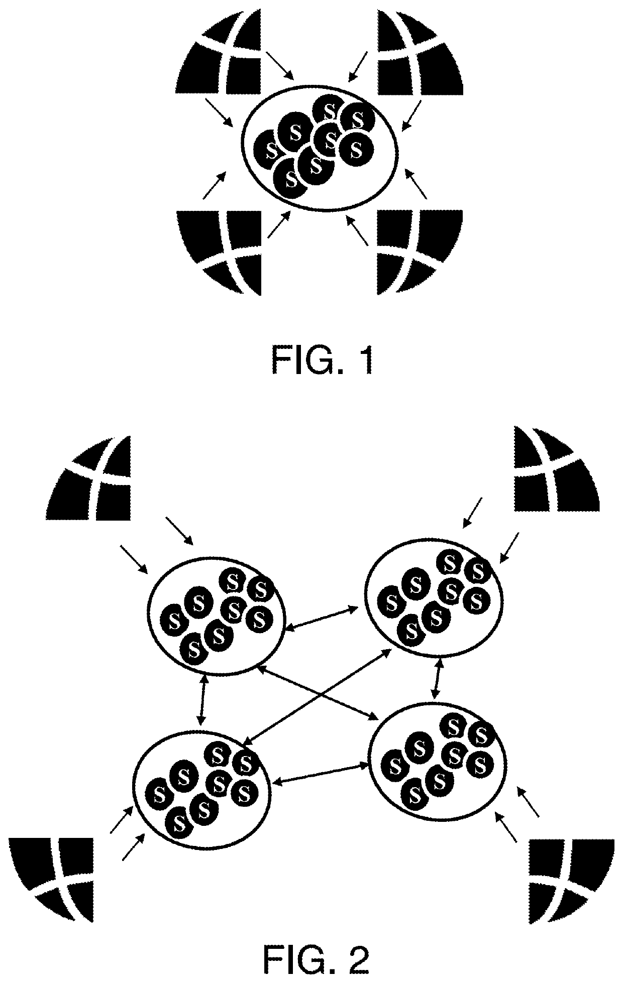
[0031]FIG. 1 shows multiple clients interacting with a central server;

[0032]FIG. 2 shows multiple clients interacting with a distributed computing architecture providing the same services as the central server of FIG. 1;

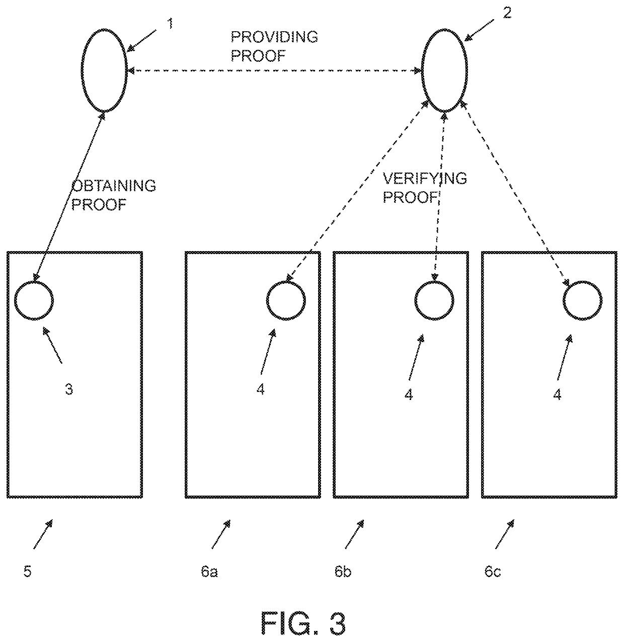
[0033]FIG. 3 shows operation of a distributed system such as that shown in FIG. 2 where distributed nodes create and verify proofs;

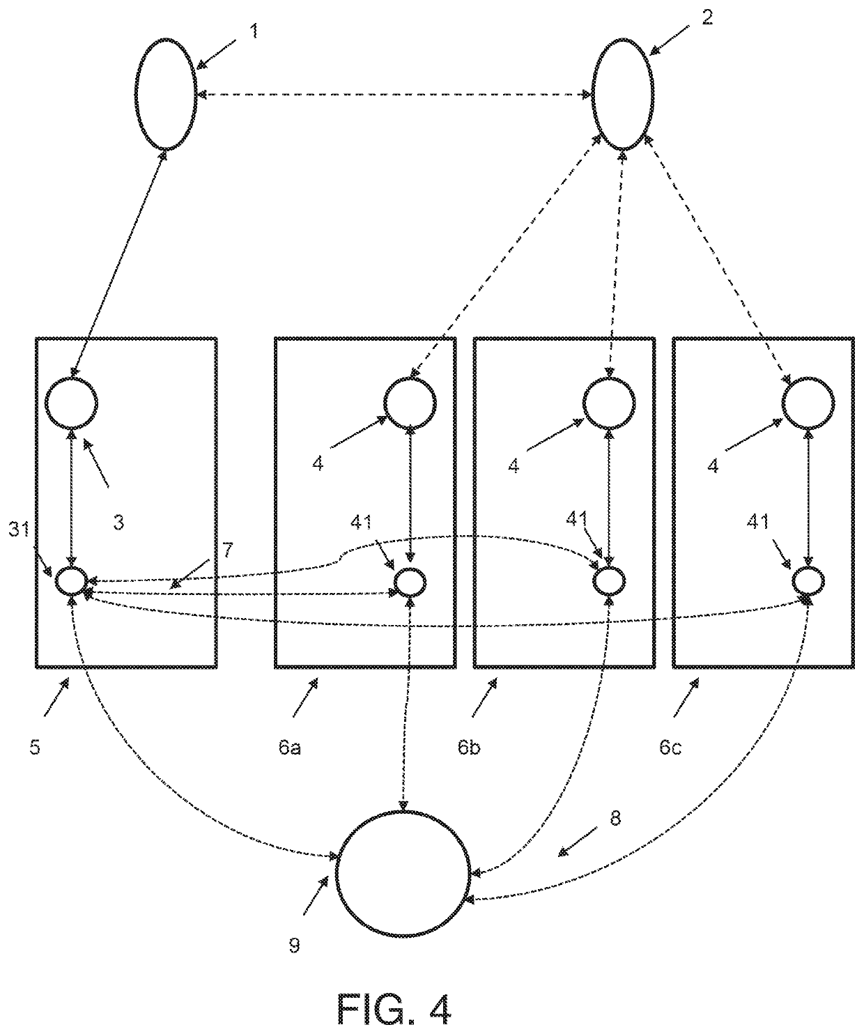
[0034]FIG. 4 shows an approach to monitoring in the arrangement of FIG. 3 according to embodiments of the disclosure FIG. 5 shows schematically a distributed transaction architecture using a four-party model;

[0035]FIG. 6 illustrates elements of a complex distributed system adapted to implement the transaction architecture of FIG. 5;

[0036]FIG. 7 shows schematically an exemplary system for enabling digital transactions in the transaction architecture of FIGS. 5 and 6;

[0037]FIG. 8 illustrates schematically ...


PUM


Abstract

A method is described of monitoring a service performed at a computing node. The computing node is one of a plurality of computing nodes in a distributed computing system. Each computing node is adapted to perform at least one service for clients. A monitoring process is adapted to monitor a service process performing the process. In the method, the monitoring process monitors the service process on performance of the service. The monitoring service then provides monitoring information to a monitoring process for another service process. A suitable computing node for performing the service is described, as is a coordinated monitoring service for supporting multiple monitoring services.

Description

FIELD OF DISCLOSURE[0001]The present disclosure relates to monitoring in a distributed computing system, in particular, a distributed computing system performing one or more secure processes.[0002]Background to Disclosure There are multiple technical challenges with requiring a centralized system to provide services to a very large number of clients, particularly when these are widely geographically distributed. It is logical to consider distributing the system so that the relevant services can be provided by a set of geographically distributed servers, rather than one central server or data centre.[0003]In practice, such decentralisation may use a cloud architecture, which will typically use a number of geographically distributed servers—or data centres—to deliver services to clients. The cloud architecture may be considered as comprising a number of nodes—when using a cloud architecture, a node may be an aggregation of a number of computers and may cover more than one data centre ...

Claims


Application Information

Patent Timeline
IPC IPC(8): G06F11/30H04L9/32G06F9/54G06F9/50
CPCG06F11/3006G06F9/5072G06F9/546H04L9/3242G06Q30/018G07F9/026G07F17/3223G06Q20/202G07F9/002G06Q20/223H04L9/32H04L63/12
Inventor RADU, CRISTIANCOLLINGE, MEHDILAAZIMANI, OMAR
Owner MASTERCARD INT INC
Learn More