Apparatus for Oil Flow Control

a technology of oil flow and apparatus, applied in the direction of combustion regulation, mechanical equipment, lighting and heating apparatus, etc., can solve the problems of not addressing the problem of varying viscosity and its effect on atomization and flame quality, requiring additional expenses for a viscometer and its maintenance, and too much or too little combustion air

Inactive Publication Date: 2021-05-13
PREFERRED UTILITIES MFG
View PDF0 Cites 2 Cited by
  • Summary
  • Abstract
  • Description
  • Claims
  • Application Information

AI Technical Summary

Benefits of technology

[0003]It is a general object of the present invention to provide a method for controlling the flow rate and the viscosity of a fuel oil to fired equipment.

Problems solved by technology

The variation in viscosity can cause a change of flow rate of the fuel to fired equipment, resulting in either too much or too little combustion air.
Using a flow meter to provide a feedback signal to a flow control valve can result in a more precise control of the fuel flow rate, but it does not address the problem of varying viscosity and its effects on atomization and flame quality.
Using a viscometer to directly control viscosity of a fuel oil requires additional expenses for a viscometer and its maintenance.

Method used


Image

  • Apparatus for Oil Flow Control
  • Apparatus for Oil Flow Control

Examples


Embodiment Construction

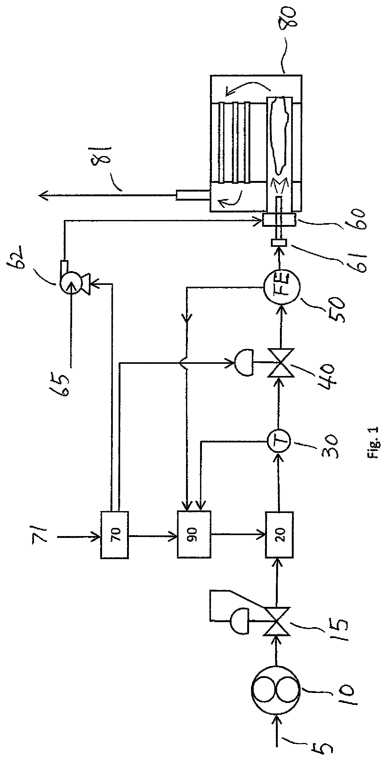
[0010]FIG. 1 is a diagram of an embodiment of the hardware configuration of the control system of the current invention.

[0011]Residual fuel oil 5 is drawn by an oil pump 10 to be pressurized, and goes through a pressure regulator 15 to reach a constant pressure downstream of the regulator 15, before going through a trim heater 20. A temperature sensor 30 measures the temperature of the fuel oil 5 and provides a feedback signal to a controller 90. Fuel oil 5 then goes through a flow control valve (FCV) 40 and a flow element 50 before it passes through the oil gun 61 to be atomized and burned in a burner 60 in a boiler 80. Boiler 80 could be a firetube boiler or a water tube boiler. The burner 60 produces a hot flue gas in boiler 80. The hot flue gas goes through the boiler and exits the boiler as flue gas 81. The flow element 50 measures the flow rate of fuel oil 5 and provides a feedback signal to the controller 90.

[0012]A combustion controller 70 takes a call-for-heat signal 71, ca...


PUM


Abstract

The current invention discloses a method of controlling the flow rate of a heavy fuel oil in a fluid transfer apparatus having a point of use outlet to a boiler. It not only controls the flow rate of the fuel oil directly, but also indirectly control the viscosity of the fuel oil without measuring its viscosity. It relies on combustion curves established during the commissioning period using a typical fuel oil at a predetermined trim heater temperature. During normal operation, it sets the flow control valve according to the combustion curves, measures the flow rate and compares to the flow rate target. Instead of using the flow rate measurement feedback to control the flow control vale, it modulates the trim heater to vary the viscosity to arrive at the desired flow rate.

Description

BACKGROUND OF THE INVENTION1. Field of the Invention[0001]This invention relates generally to control of fuel oil to fired equipment such as a boiler. More particularly, it is directed to the control of both the flow rate and the viscosity of a fuel oil using a flow control valve and a trim heater.2. Description of the Related Art[0002]Residual fuel oils such as #6 oil vary in viscosity by batch and location of origin. The variation in viscosity can cause a change of flow rate of the fuel to fired equipment, resulting in either too much or too little combustion air. Furthermore, change in viscosity can also influence the atomization quality and the flame stability. In most residual fuel burning applications, a trim heater is used to heat the fuel to a desired temperature directly before ignition in the fired equipment. The trim heater is typically set to a pre-determined temperature setting (for example 180° F.) and will maintain that temperature regardless of flow rate or fuel prop...

Claims


Application Information

Patent Timeline
Patent Type & Authority Applications(United States)
IPC IPC(8): F23N1/00F23C9/00F23D11/10F23N5/02F23N5/18
CPCF23N1/005F23C9/00F23D11/101F23N5/022F23N5/18F23N2041/04F23N2021/04F23N2021/12F23N2023/04F23N2039/06F23N2005/185F23N1/002F23N2221/04F23K2300/204F23K2300/206F23N2221/12F23N2223/04F23N2239/06F23N2241/04
Inventor WALLACE, DANIEL P.
Owner PREFERRED UTILITIES MFG
Why Eureka
Try Eureka