Digital denture manufacturing method and manufacturing system, and denture hole guider applied thereto and manufacturing method thereof

Active Publication Date: 2021-05-27
DIO
View PDF0 Cites 0 Cited by
  • Summary
  • Abstract
  • Description
  • Claims
  • Application Information

AI Technical Summary

Benefits of technology

The invention provides a solution for designing and manufacturing digital dentures using a 3D work image and acquiring surface profiles of a target dental arch and implant information of a fixture using a temporary denture and a support cylinder. The invention also allows for easy replacement and correction of the surface profile and improves accuracy in the engagement groove and binding groove of the digital denture. Additionally, the invention provides a simple method for converting a previously used adhesive type denture into a temporary denture that can be installed in a target dental arch through a fixture and support cylinder using a denture hole guider.

Problems solved by technology

As such, the installation process of the denture becomes quite complicated, and the cured resin has a weak support force for a body of the denture and is easily separated, and thus the installation stability and durability of the denture are lowered.
However, the impression acquisition method described above causes discomfort to a denture subject due to a foreign material sensation when the impression is being acquired.
In addition, the burden of the operator is increased due to a large number of process steps being complicated and having a high level of difficulty, and errors of each process step are often accumulated, which causes a degradation of precision.

Method used


Image

  • Digital denture manufacturing method and manufacturing system, and denture hole guider applied thereto and manufacturing method thereof
  • Digital denture manufacturing method and manufacturing system, and denture hole guider applied thereto and manufacturing method thereof
  • Digital denture manufacturing method and manufacturing system, and denture hole guider applied thereto and manufacturing method thereof

Examples


Embodiment Construction

[0032]Hereinafter, example embodiments of the present invention will be described with reference to the accompanying drawings in detail.

MODES OF THE INVENTION

[0033]Hereinafter, a digital denture manufacturing method and manufacturing system, a denture hole guider applied to the manufacturing method and manufacturing system, and a manufacturing method of the denture hole guider according to embodiments of the present invention will be described with reference to the accompanying drawings.

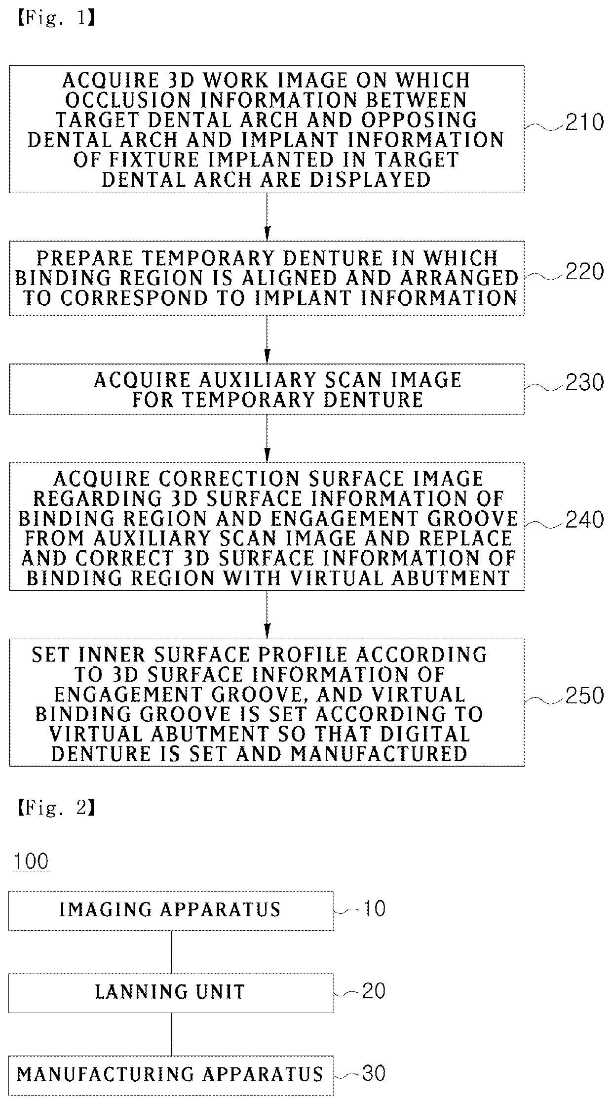
[0034]FIG. 1 is a flowchart showing a digital denture manufacturing method according to an embodiment of the present invention, and FIG. 2 is a block diagram illustrating a digital denture manufacturing system according to an embodiment of the present invention.

[0035]Referring to FIGS. 1 to 2, the digital denture manufacturing method according to the present invention includes acquiring a three-dimensional (3D) work image (210), preparing a temporary denture (220), acquiring an auxiliary scan image (...


PUM


Abstract

In order to improve manufacturing convenience and precision, the present invention provides a digital denture manufacturing method comprising: a first step of acquiring a three-dimensional work image, on which occlusion information between a target dental arch and an opposing dental arch and implant information of a fixture implanted in the target dental arch are displayed, and preparing a temporary denture in which a binding region formed to correspond to a binding portion profile of an abutment fastened to the fixture is arrayed and arranged; a second step of acquiring an auxiliary scan image for the temporary denture; a third step of acquiring, from the auxiliary scan image, a correction surface image on three-dimensional surface information of an inner surface-side engagement groove of the temporary denture including the binding region; and a fourth step of designing and manufacturing a digital denture having a virtual binding groove corresponding to the position and the shape of the three-dimensional surface information of the binding region, in an inner surface profile set according to the three-dimensional surface information of the engagement groove.

Description

TECHNICAL FIELD[0001]The present invention relates to a digital denture manufacturing method and manufacturing system, a denture hole guider applied to the manufacturing method and manufacturing system, and a manufacturing method of the denture hole guider, and more specifically, to a digital denture manufacturing method and manufacturing system, a denture hole guider applied to the manufacturing method and manufacturing system, and a manufacturing method of the denture hole guider, which ensure an improved manufacturing convenience and precision.BACKGROUND ART[0002]Generally, false teeth or dentures refer to intraoral artificial periodontium that artificially restore an appearance and functions by replacing missing natural teeth. Such false teeth or dentures may be installed inside the oral cavity to restore a mastication function and prevent deformation of periodontium and may be divided into partial / complete false teeth and partial / complete dentures according to the number of mis...

Claims


Application Information

Patent Timeline
IPC IPC(8): A61C13/00A61C13/107A61C9/00A61C1/08G16H30/40
CPCA61C13/0004A61C13/0001G16H30/40A61C1/084A61C9/0046A61C8/00A61C9/00A61C13/00A61C13/24A61C19/05A61C8/0095A61C9/0053A61C13/34G06T19/20
Inventor CHOI, BYUNG HOJUNG, SEUNG MLKIM, JIN CHEOLKIM, JIN BAEK
Owner DIO
Why Eureka
Try Eureka