Flexible reactive power compensation

a reactive power compensation and flexible technology, applied in the direction of reactive power adjustment/elimination/compensation, electrical equipment, ac network circuit arrangement, etc., to achieve the effect of reducing coupling, effective dampening harmonics produced, and improving reactive power compensation

Active Publication Date: 2021-05-27
SIEMENS ENERGY GLOBAL GMBH & CO KG
View PDF0 Cites 0 Cited by
  • Summary
  • Abstract
  • Description
  • Claims
  • Application Information

AI Technical Summary

Benefits of technology

[0021]According to an embodiment of the present invention, a first impedance of the transformer between the primary coil and the first secondary coil is higher than a second impedance of the transformer between the primary coil and the second secondary coil, thereby enabling damping harmonics generated be the first group of power electronic switches.
[0022]For example, the first group of reactive power compensation devices may produce higher amplitudes of harmonics (of a base or fundamental AC frequency which may be for example 50 Hz or 60 Hz) than the second group of reactive power compensation devices. In particular, the first impedance (in particular for the expected or actual harmonics produced by the first group of reactive power compensation devices) may be higher than the second impedance (for the same frequency range, in particular), to effectively dampen the harmonics produced by the first group of reactive power compensation devices. The required first impedance may be achieved by appropriately constructing the secondary coil regarding winding topology, material of the wire, material of the stator core, etc., as is known to the skilled person. Thereby, the reactive power compensation may be further improved.
[0023]According to an embodiment of the present invention, the second secondary coil is substantially decoupled from the first secondary coil. Thereby, it may be achieved to reduce a coupling between the secondary coils in order to reduce influence of the harmonics produced by the first group of compensation devices to the second group of compensation devices. Decoupling may be achieved by appropriately separating any coil windings of the second secondary winding from windings of the first secondary winding.

Problems solved by technology

It has however been observed that the conventional systems and methods for providing reactive power compensation have several problems or disadvantages for compensating reactive power as required or demanded by a grid operator, for example.

Method used


Image

  • Flexible reactive power compensation

Examples


Embodiment Construction

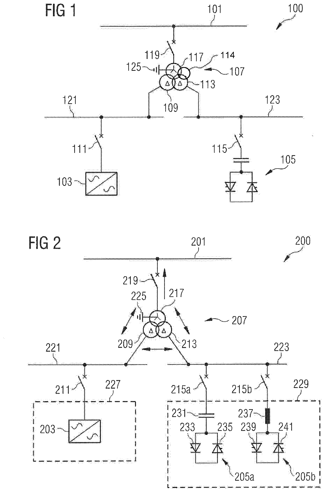
[0037]The illustration in the drawings is in schematic form. It is noted that in different figures, similar or identical elements are provided with the same reference signs or with reference signs, which are different from the corresponding reference signs only within the first digit.

[0038]The arrangement 100 for reactive power compensation at an electric energy transmission line 101 comprises a first reactive power compensation device 103 comprising a first type of power electronic switches. The arrangement 100 further comprises a second reactive power compensation device 105 comprising a second type of power electronic switches. The arrangement 100 further comprises a transformer 107 having a first secondary coil 109 connected to the first reactive power compensation device 103 via a switch 111. Thus, the first reactive power compensation device 103 is connectable to the first secondary coil 109 of the transformer 107. The transformer 107 further comprises a second secondary coil ...


PUM


Abstract

An arrangement for reactive power compensation at an electric energy transmission line includes at least one first reactive power compensation device including a first type of power electronic switches, at least one second reactive power compensation device including a second type of power electronic switches and a transformer having a first secondary coil connected to the first device, a second secondary coil connected to the second device and a primary coil connectable to the electric energy transmission line. The primary coil has more windings than any of the first and second secondary coils.

Description

FIELD OF INVENTION[0001]The present invention relates to an arrangement and to a method for reactive power compensation at an electric energy transmission line.ART BACKGROUND[0002]An electric transmission line may transmit active power and reactive power over wide distances at high voltage. The electric energy transmission line may be connected to a utility grid operated by a grid operator. The grid operator may require different amounts of reactive power supplied to the utility grid. Thus, it may be required to provide equipment connectable to the electric energy transmission line which enables consumption and / or production of reactive power, such as capacitive reactive power and / or inductive reactive power.[0003]Conventionally, passive or active devices have been used for this purpose. For example, passive devices may include a capacitor or an inductor which may for example be shunt-connected to the electric energy transmission line. Active devices may include high power switches,...

Claims


Application Information

Patent Timeline
Patent Type & Authority Applications(United States)
IPC IPC(8): H02J3/18H02J3/22H02J3/20
CPCH02J3/1842H02J3/20H02J3/1864H02J3/22
Inventor WIESINGER, MARKUSKYNEV, SERGEY
Owner SIEMENS ENERGY GLOBAL GMBH & CO KG
Why Eureka
Try Eureka