Laser assisted machining of sheet material

Pending Publication Date: 2021-06-03
IPG PHOTONICS CORP
View PDF0 Cites 0 Cited by
  • Summary
  • Abstract
  • Description
  • Claims
  • Application Information

AI Technical Summary

Benefits of technology

[0007]In addition, a system and process where the scored portion of the sheet material that includes the scored lines is subjected to a flattening process prior to the punching operation is disclosed. Performing the flattening operation prior to the punching operation has the effect of streamlining the process. That is, the sheet material can be easily handled and conveyed from the scoring process and any cutting process, through the flattening process, and to the separation process without need for separate handling of the component. Such streamlining is of particular value when handling thin sheets that, in some cases, resemble foil material. Herein, “sheet material” is construed broadly to include conventional sheets, ribbons, thin plates, reels, coils and other such forms that may be processed in a stamping or through-punch operation.
[0008]The flattening process acts to return the cut and/or scored portion of the sheet material to substantially the original thickness by flattening proud features that may arise in the cutting or scoring processes, such as dross or beads of molten materials which may form at the corners of the scored grooves. The cut and/or scored portion of the sheet may undergo some degree of bowing or warping due to the temperature gradients that are incurred during the cutting and scoring processes. The flattening process may remove or diminish such bowing or warping and restore the scored portion of the sheet material to a planar state.
[0009]Another aspect of the disclosed systems and processes are that the

Problems solved by technology

The cut and/or scored portion of the sheet may undergo some degree of bowing or warping due to the temperature gradients that are incurred during the cutting and

Method used


Image

  • Laser assisted machining of sheet material
  • Laser assisted machining of sheet material
  • Laser assisted machining of sheet material

Examples


Example

DETAILED DESCRIPTION OF THE FIGURES

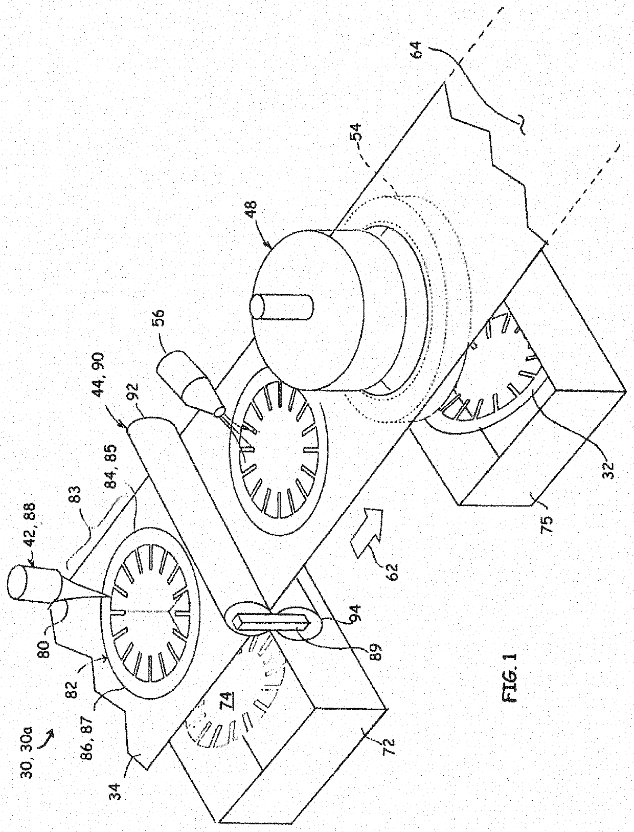
[0035]Referring to FIG. 1, a scoring-assisted system 30a for fabricating components 32 from a sheet material 34 is depicted according to an embodiment of the disclosure. In the depicted embodiment, the scoring-assisted system 30a includes a scanning radiation source 42, a sheet flattening device 44, a component punch 48, and a component die 54. Also in the depicted embodiment is an air nozzle 56 directed at the sheet material 34. A discard bin 72 may be configured to receive discards 74 that are removed from the sheet material 34 by scanning radiation source 42. The discards 74 may be a single continuous piece (depicted) or may be a plurality of pieces (e.g., a plurality of isolated apertures). Likewise, a component bin 75 may be configured to receive components 32 that are removed from the sheet material 34 by the component punch 48.

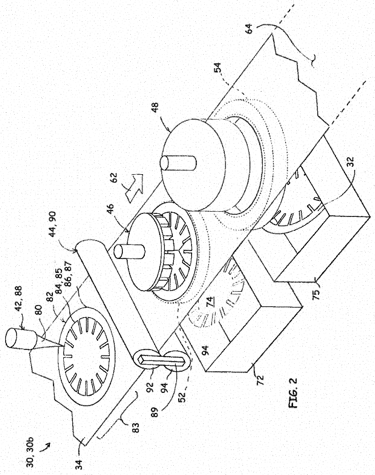
[0036]Referring to FIG. 2, a scoring-assisted system 30b for fabricating the components 32 from the sheet material 3...


PUM

PropertyMeasurementUnit
Fractionaaaaaaaaaa
Fractionaaaaaaaaaa
Fractionaaaaaaaaaa

Abstract

A system and process for fabricating components from sheet material. Various embodiments of the disclosure combine punching of components from sheet material with a scoring process that outlines the components prior to the punching operation. In addition, a system and process where the scored portion of the sheet material that includes the scored outline is subjected to a high compression flattening process prior to the punching operation is disclosed. Performing the flattening operation prior to the punching operation has the effect of streamlining the process. That is, the sheet material can be easily handled and conveyed from the scoring process, through the flattening process, and to the punching process without need for separate handling of the component.

Description

RELATED APPLICATIONS[0001]This application claims the benefit of U.S. Provisional Application No. 62 / 657,242, filed Apr. 13, 2018, the disclosure of which is incorporated by reference herein in its entirety.FIELD OF THE DISCLOSURE[0002]This application is directed generally to methods and systems for fabricating components from sheet stock, and more specifically laser machining of sheet stock in tool and die fabrication processes and systems.BACKGROUND OF THE DISCLOSURE[0003]A wide range of sheet metal parts are manufactured by stamping and punching from sheet stock. Conventionally, the gap between the die and punch requires tight clearances, typically 5% to 15% of material thickness. For thin sheet stock, the die and the punch must be machined within tolerances to provide the required fit.[0004]Furthermore, certain materials are not conducive to stamping or punching. An example of difficult materials to stamp or punch is electrical steels, which, due to normal wear and tear of the ...

Claims


Application Information

Patent Timeline
IPC IPC(8): B23K26/00B23K26/40B21D1/02B21D28/10B23K26/082B23K26/364
CPCB23K26/0093B23K26/40B21D1/02B23K2101/16B23K26/082B23K26/364B21D28/10B23K26/0846B23K2103/04B21D28/18B21D28/22B23P15/00B23P2700/12B23K26/384B21D28/14B21D28/34B21D45/02B23P13/02
Inventor LEV, LEONID C.MUELLER, STEFFEN
Owner IPG PHOTONICS CORP
Why Eureka
Try Eureka