
A vision system for a motor vehicle and a method of training

a vision system and motor vehicle technology, applied in adaptive control, process and machine control, instruments, etc., can solve the problems of difficult to achieve, difficult to achieve, and difficult to achieve, so as to improve the reliability of power mode classification and/or high-power mode request, and reduce heat generation. , the effect of special energy-efficient and/or dedicated hardwar

Pending Publication Date: 2021-06-03
ARRIVER SOFTWARE AB
View PDF8 Cites 0 Cited by
  • Summary
  • Abstract
  • Description
  • Claims
  • Application Information

AI Technical Summary

Benefits of technology

The patent describes a data processing device that reduces heat generation and saves processing resources by deactivating high-power applications in the low-power mode. This is done by a controller that transmits control signals to switch the high-power applications off and activates low-power applications and a power mode classifier when needed. The technical effect is reduced heat generation and simplified data management.

Problems solved by technology

For example, in windshield mounted automotive applications, thermal management is a crucial problem due to the difficulty of the dissipation of heat generated by the electronics of the vision system, in particular by the data processing device.
However, when the vehicle is stationary, the problem becomes severe and often requires specific low-power modes of the data processing device in order to reduce the amount of heat generated by the vision system.
In autonomous or semi-autonomous vehicles, the problem is particularly complex due to the heat generation of the data processing device by the execution of computationally complex algorithms such as object detection.
However, to provide detectors and controllers which are cost-effective, computationally effective and robust enough for all different situations that are of interest remains a problem.

Method used


Image

  • A vision system for a motor vehicle and a method of training
  • A vision system for a motor vehicle and a method of training

Examples


Embodiment Construction

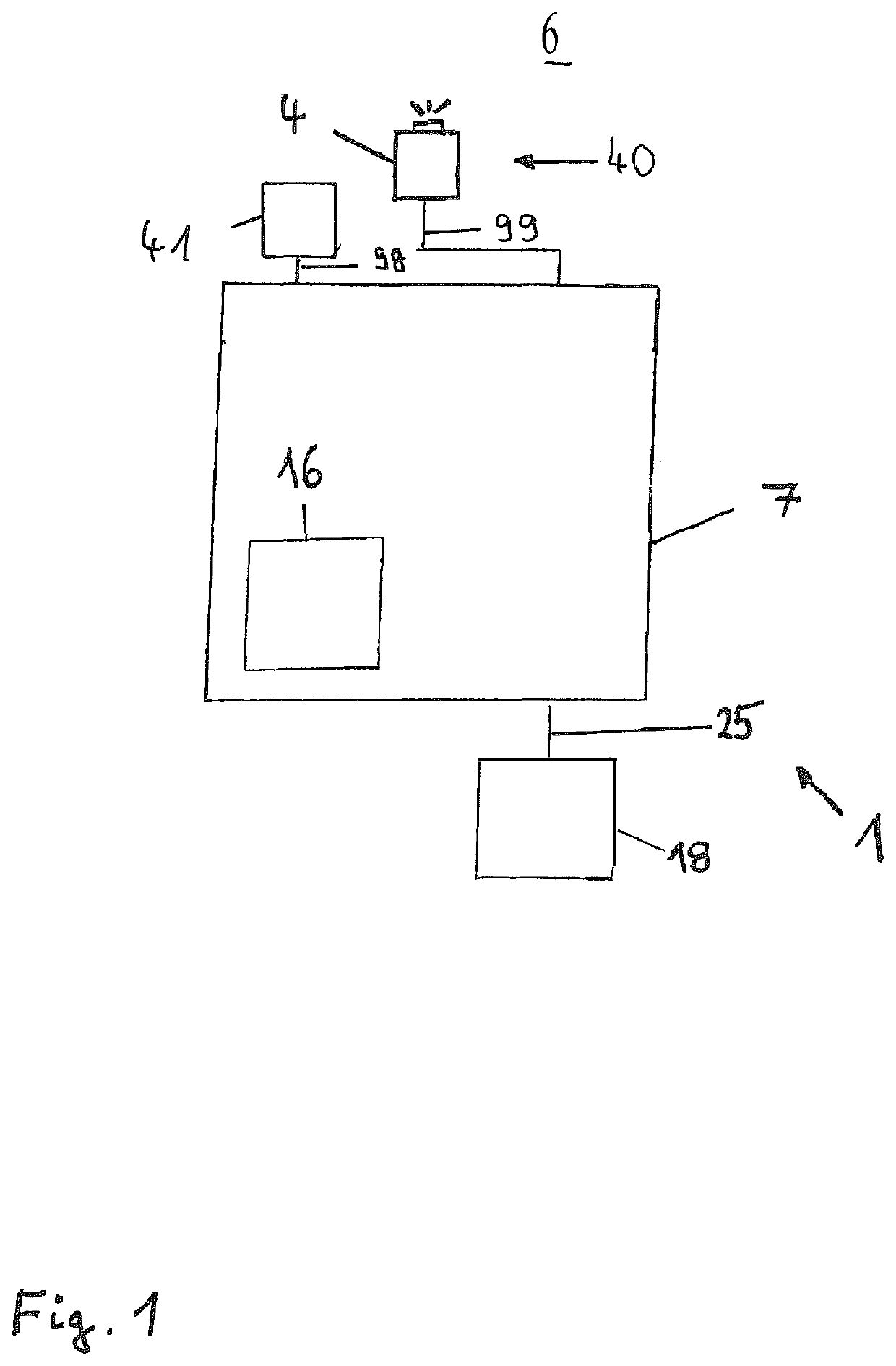
[0034]In FIG. 1, a vision system 1 mounted in a motor vehicle comprises a sensing device 40 for sensing data of the motor vehicle and / or a region surrounding 6 the motor vehicle. The sensing device 40 can be coupled to an on-board data processing device 7 adapted to process the sensed data received as input data 99 from the sensing device 40.

[0035]In this embodiment, the sensing device 40 comprises an imaging apparatus for capturing images of the region surrounding 6 the motor vehicle, for example a region in front of the motor vehicle. The imaging apparatus comprises one or more optical imaging devices 4, in particular cameras, preferably operating in the visible and / or infrared wavelength range, where infrared covers near IR with wavelengths below 5 microns and / or far IR with wave-lengths beyond 5 microns.

[0036]In some embodiments the imaging apparatus comprises a plurality of imaging devices 4 in particular forming a stereo imaging apparatus. In other embodiments only one imaging...


PUM


Abstract

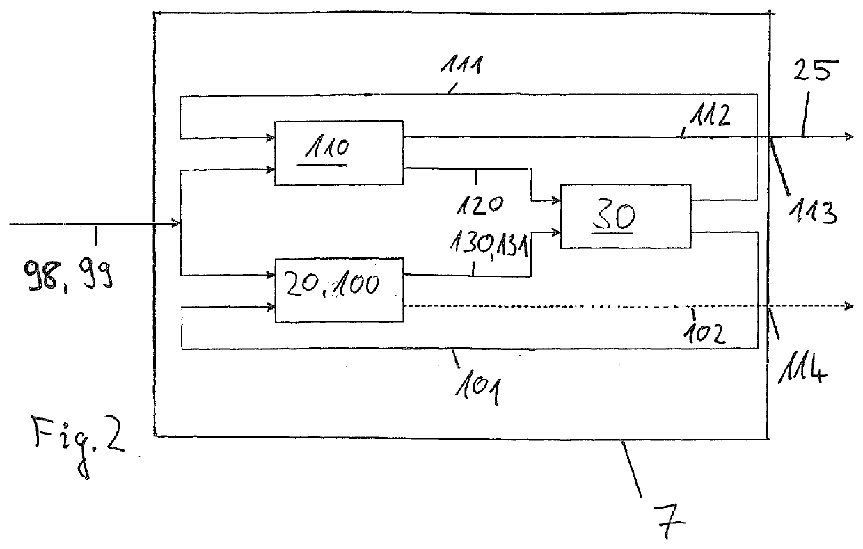
A vision system (1) for a motor vehicle, includes a sensing device (40) adapted to sense data (99), a data processing device (7) adapted to process the sensed data (99), wherein the data processing device (7) includes a controller (30) adapted to switch a power mode of the data processing device (7) between a low-power mode and a high-power mode, wherein a high-power application (110) can be executed in the high-power mode. The data processing device (7), in a low-power mode, is adapted to execute a power mode classifier (20), and the power mode classifier (20) is adapted to classify any input data (99) from the sensing device (40) as requiring executing the high-power application (110) or not, and to output a high-power mode request (130) to the controller (30) to switch the power mode of the data processing device (7) from the low-power mode to the high-power mode in case the power mode classifier (20) has classified the input data (99) as requiring executing the high-power application (110).

Description

CROSS-REFERENCE TO RELATED APPLICATIONS[0001]This application is a 35 U.S.C. § 371 national phase of PCT International Application No. PCT / EP2019 / 071722, filed Aug. 13, 2019, which claims the benefit of priority under 35 U.S.C. § 119 to European Patent Application No. 18189354.6, filed Aug. 16, 2018, the contents of which are incorporated herein by reference in their entirety.FIELD OF THE INVENTION[0002]The invention relates to a vision system for a motor vehicle, comprising a sensing device adapted to sense data, a data processing device adapted to process the sensed data, wherein the data processing device comprises a controller adapted to switch a power mode of the data processing device between a low-power mode and a high-power mode, wherein a high-power application can be executed in the high-power mode. The invention relates also to a method of training a software component for a vision system.BACKGROUND AND INTRODUCTORY DESCRIPTION OF EXEMPLARY EMBODIMENTS[0003]For example, i...

Claims


Application Information

Patent Timeline
Patent Type & Authority Applications(United States)
IPC IPC(8): B60W50/06G05B13/02G06V10/764
CPCB60W50/06G05B13/029B60W2050/0095B60W2420/52B60W2420/42G06F1/3206G06V20/56G06V10/454G06V10/82G06V10/764H04N23/65G06F1/3287B60W2050/0091B60W2520/04B60W2420/403B60W2420/408
Inventor JAGBRANT, GUSTAVCRONVALL, PER
Owner ARRIVER SOFTWARE AB
Learn More