
Method and device for determining the cause of a fault in an electrical circuit

a technology of electrical circuit and fault, applied in the direction of process and machine control, testing/monitoring control system, instruments, etc., can solve the problems of inability to determine the exact location and the logical and/or temporal association with the cause of the fault only with difficulty

Pending Publication Date: 2021-06-03
SIEMENS AG
View PDF0 Cites 0 Cited by
  • Summary
  • Abstract
  • Description
  • Claims
  • Application Information

AI Technical Summary

Benefits of technology

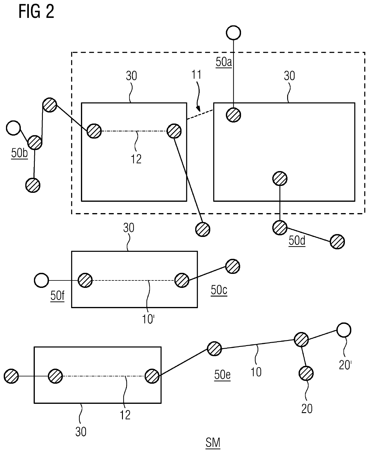
The present invention provides a computer-supported simulation tool for analyzing the faults of an electrical circuit. This tool allows for a real-time simulation of the circuit's switching operation and the modeling of a large number of faults and their effects. It reduces the complexity of modelling by using a graph-based approach and propositional logic representation. The invention also describes the known union-find algorithm for efficiently determining the connected components of the graph and potential levels. Overall, the invention simplifies the analysis of electrical circuit faults and provides a more effective tool for identifying and troubleshooting technical problems.

Problems solved by technology

During the operation of machine tools, machine outages can frequently occur, the cause of which is attributable to the electrical circuit thereof.
An outage can be caused, for example, by a short-circuit or a cable break.
However, on the grounds of the complexity of an electrical circuit of a conventional machine tool, in many cases, the exact location and the logical and / or temporal association with the cause of a fault can only be determined with difficulty.
These approaches can be complex, or can result in a prolonged downtime of the affected machine.

Method used


Image

  • Method and device for determining the cause of a fault in an electrical circuit
  • Method and device for determining the cause of a fault in an electrical circuit
  • Method and device for determining the cause of a fault in an electrical circuit

Examples


Embodiment Construction

[0033]The following exemplary embodiments represent exemplary possibilities of execution only, wherein such executions might be considered to constitute the instruction incorporated in embodiments of the invention, on the grounds that it is not possible, and is neither expedient nor necessary for the understanding of embodiments of the invention, for all these possibilities of execution to be specified.

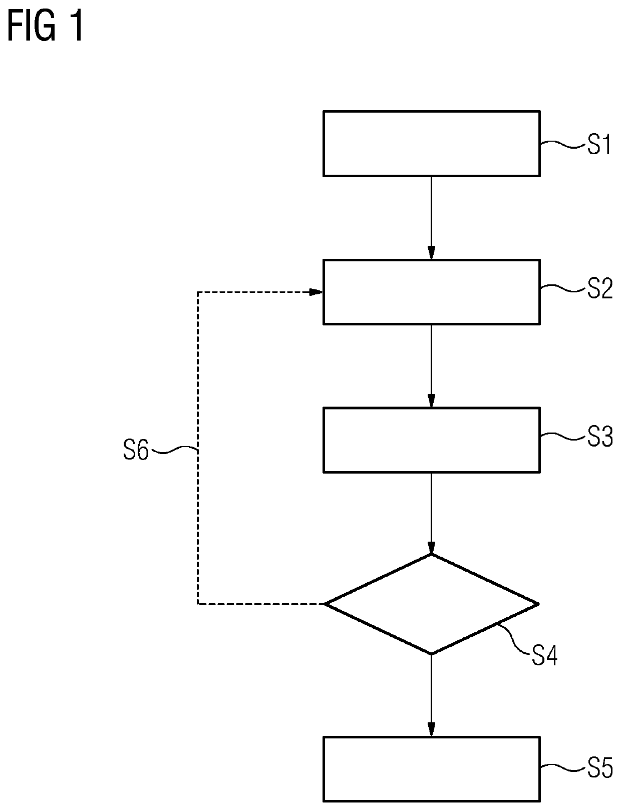
[0034]FIG. 1 shows a flow diagram of a computer-implemented method for determining the cause of a fault in an actual electrical circuit. This can involve, for example, a defect in the electrical circuit of a machine tool. The cause and / or location of the defect can be efficiently determined by the computer-implemented method, for example, in parallel with the operation of the actual machine tool.

[0035]In the first step S1 of the computer-implemented method, a graph-based circuit diagram simulation model of the electrical circuit is inputted. The graph-based circuit diagram simulation ...


PUM


Abstract

Provided is a method and device for determining the cause of a fault in an electrical circuit by a graph-based circuit diagram simulation model of the electrical circuit. A fault is simulated in the electrical circuit and resulting connected components, and respective potential values and / or phase values of the graph vertices of the resulting connected components, are determined by reference to the modified graph-based circuit diagram simulation model, and, on the basis of the potential values and / or phase values of the graph vertices determined, the switching behavior of the electrical circuit is represented by the further addition and / or removal of at least one further graph edge. The resulting potential and / or phase values for specified graph vertices are outputted in the form of simulated output signals. The simulated output signals are compared with reference output signals for the electrical circuit, and the cause of the fault is outputted.

Description

CROSS-REFERENCE TO RELATED APPLICATIONS[0001]This application claims priority to European Application No. 19212213.3, having a filing date of Nov. 28, 2019, the entire contents of which are hereby incorporated by reference.FIELD OF TECHNOLOGY[0002]The following relates to a computer-implemented method and a device for determining the cause of a fault in an electrical circuit by a graph-based circuit diagram simulation model.BACKGROUND[0003]During the operation of machine tools, machine outages can frequently occur, the cause of which is attributable to the electrical circuit thereof. An outage can be caused, for example, by a short-circuit or a cable break. However, on the grounds of the complexity of an electrical circuit of a conventional machine tool, in many cases, the exact location and the logical and / or temporal association with the cause of a fault can only be determined with difficulty. Determining the cause of a fault is generally based upon catalogs, in which potential ca...

Claims


Application Information

Patent Timeline
IPC IPC(8): G01R31/28G06F30/392
CPCG01R31/2803G06F2119/02G06F30/392G06F30/367G05B23/0275G05B17/02
Inventor BOTERO HALBLAUB, ANDRÉSFISCHER, JANHERZ, MATTHIASOSWALD, WILHELMWINCHERINGER, CHRISTOPH
Owner SIEMENS AG
Learn More