Electrical probe

a multimeter and probe technology, applied in the field of electronic multimeter systems and methods, can solve the problems of misplaced terminals, long terminals, and inability to maneuver in tight spaces, and achieve the effect of maximizing safety during use and easily and conveniently measuring attributes

Active Publication Date: 2021-06-17
INNOVA ELECTRONICS
View PDF0 Cites 2 Cited by
  • Summary
  • Abstract
  • Description
  • Claims
  • Application Information

AI Technical Summary

Benefits of technology

[0009]A probe device is disclosed for applying power to, or alternatively for measuring attributes (e.g. voltage, current) of, an electronic circuit under test. The probe device typically has a user interface opposite a finger-gripping surface of a grip. The user interface allows a user to switch the probe device between discrete modes, such as a mode that measures attributes of the electronic circuit under test and a mode that applies power to the electronic circuit under test. The user interface preferably defaults to be in a mode that does not apply power to the electronic circuit under test when a user is not actively applying pressure to the user interface. This maximizes safety during use, so that a forgetful user does not accidentally apply power to themselves. Since the user interface is located opposite the finger-gripping surface of the grip, the probe device has the ability to allow a user to easily and conveniently measure attributes (e.g. voltage, current) of an electronic circuit under test, apply power to an electronic circuit under test, apply ground to an electronic circuit under test, and control operation of the probe device—all with only one hand.

Problems solved by technology

Such multimeters, however, can be rather clumsy to use, as the user needs to first find a suitable location to place the multimeter housing, place the housing down on the suitable location, turn the dial, and then use both hands to apply the multimeter terminals to the electronic device while preventing wires connecting the terminal to the housing from pulling the housing away from its location.
Other types of terminals with longer wires could be attached to the multimeter, but storing and organizing the different types of terminals within reach of a user can be troublesome, resulting in misplaced terminals.
Moreover, the long, pen-like terminals are not easily maneuverable in tight spaces.
Applying alligator clips while reaching around an obstruction, however, is quite difficult without a clear line of sight, and the ability of alligator clips to navigate such areas are limited by the size and configuration of the alligator clips themselves.
Cruz' device is also rather clumsy to use, as the user, again, needs to first find a suitable location to place the housing of the electrical test device, place the electrical test device down on the suitable location, apply the alligator clips to a test location, then activate Cruz' keypad to simultaneously apply power and measure parameters, such as voltage, to the device under test.
Such a device can be dangerous to use, as a user may forget to turn off Cruz's power sourcing functionality before removing the alligator clips.
This is particularly problematic if Cruz' alligator clips are applied to a test location behind an obstruction, as a user reaching around an obstruction may accidentally touch a conductive area of the alligator clip if the user cannot see behind the obstruction.

Method used


Image

  • Electrical probe
  • Electrical probe
  • Electrical probe

Examples


Embodiment Construction

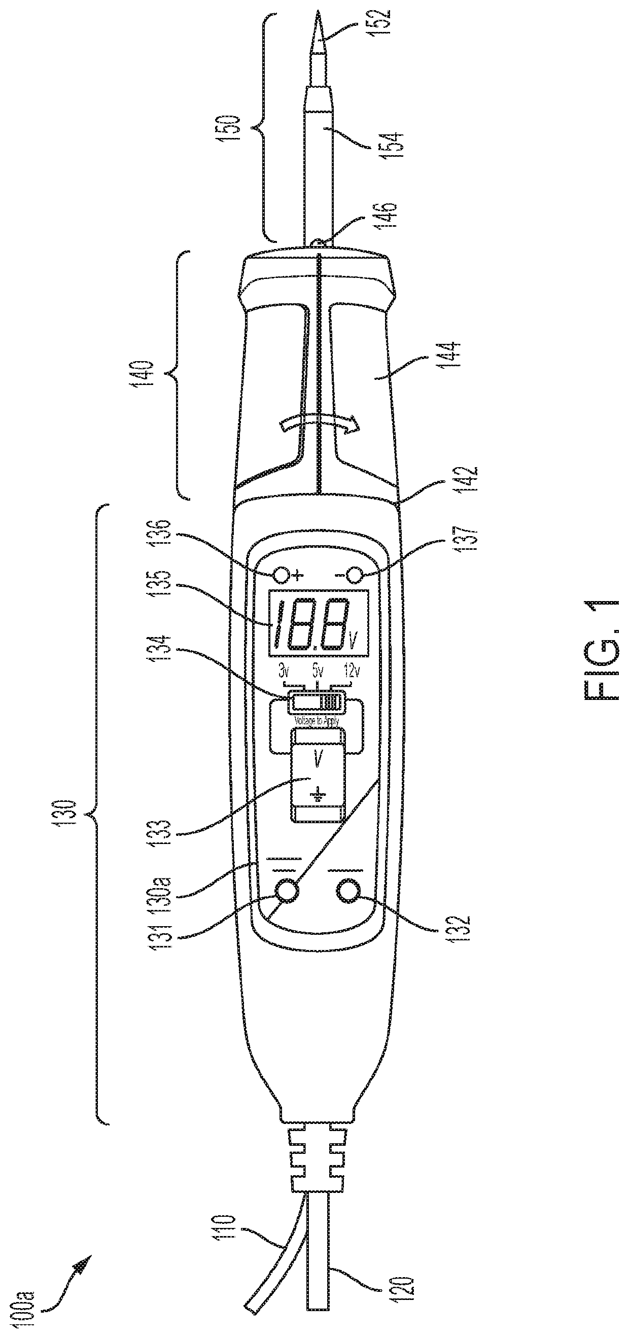
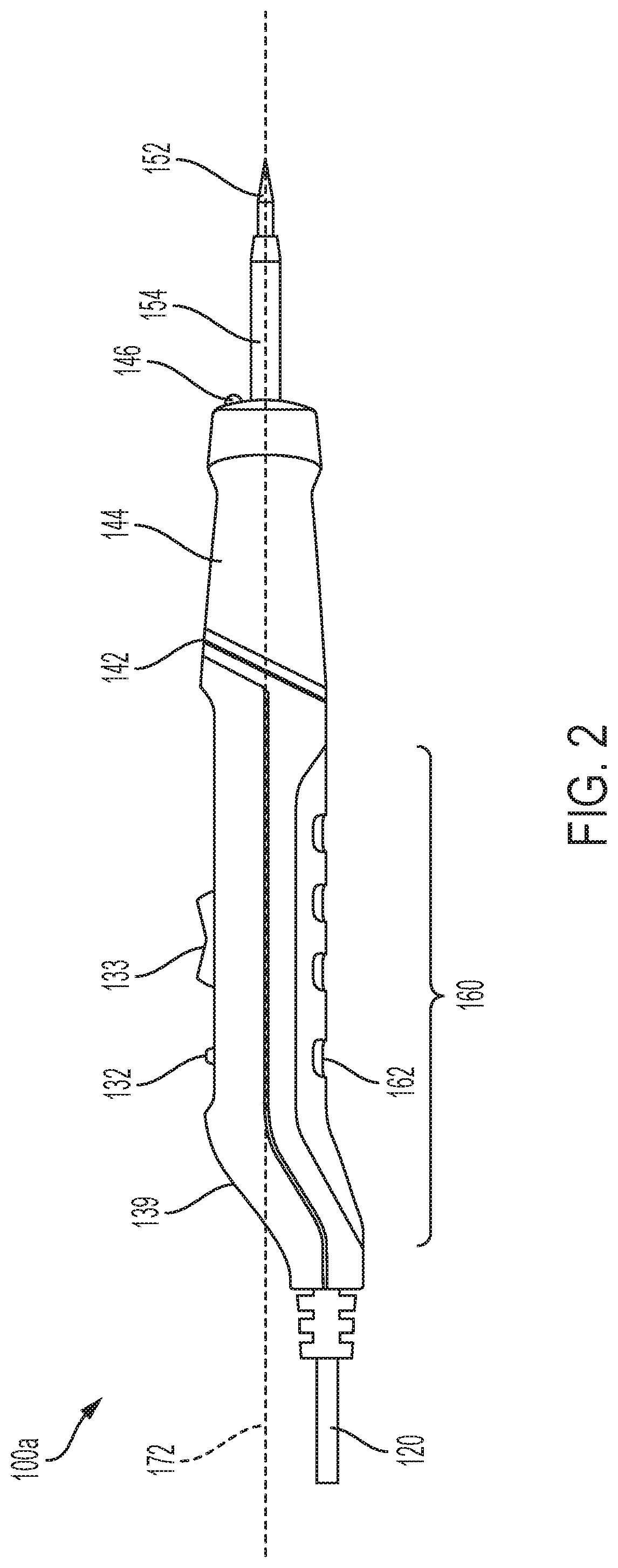
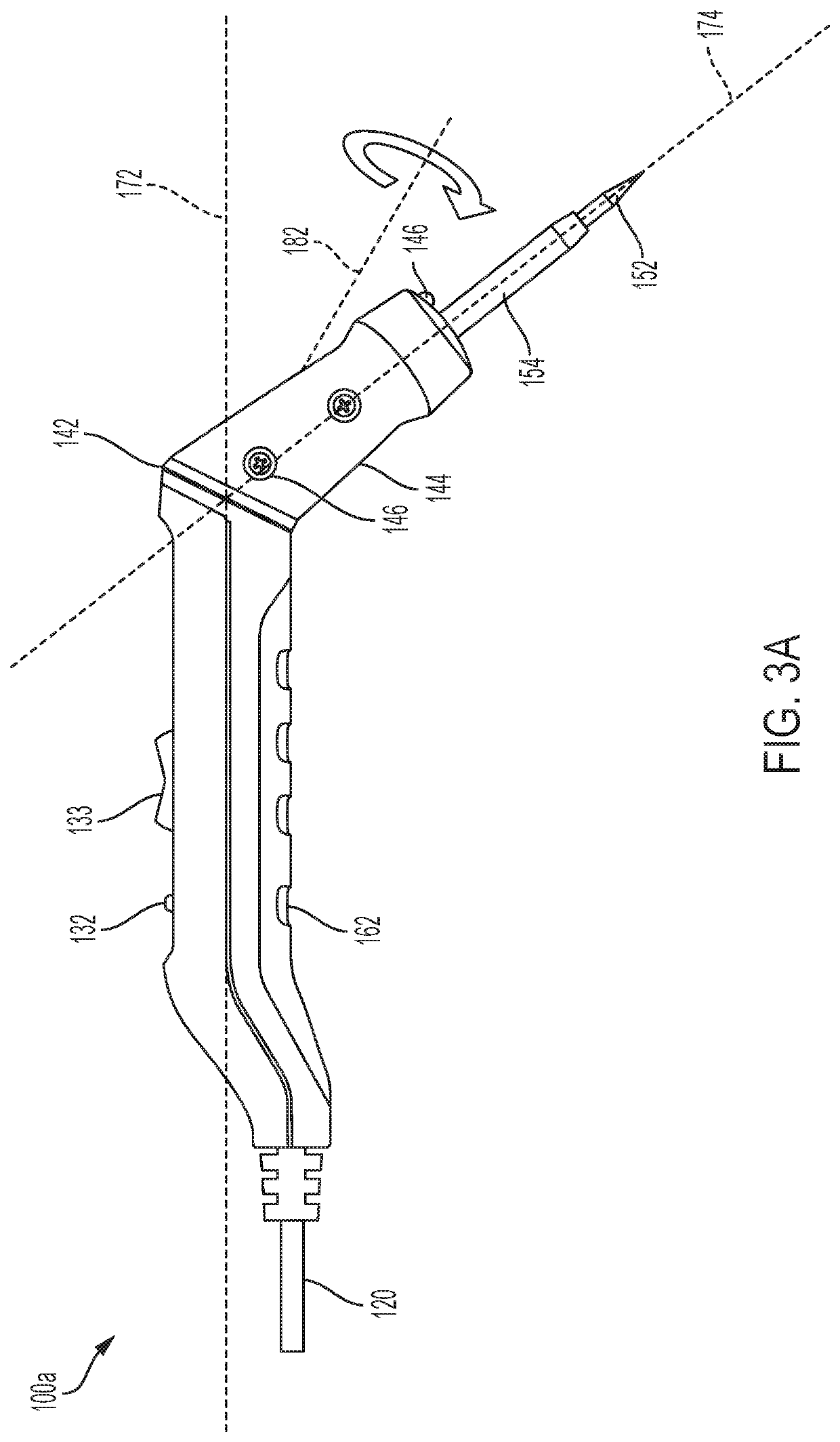
[0027]Referring now to the drawings, various embodiments of a probe device are shown for measuring attributes and / or applying power to an electronic circuit under test.

[0028]Probe device 100a, shown in FIGS. 1-3A, can have rotatable probe body 140 that allows a user to extend the conductive tip 152 of probe connector 150 into areas which are difficult to reach into with a straight probe body. A user may apply the conductive probe tip 152 to a conductive surface of an electronic circuit under test where the conductive surface is blocked by an obstruction that cannot accommodate the straight probe device 100a shown in FIG. 2 from reaching. The user may then rotate probe body 140 relative to main body 130 as shown in FIG. 3A to change the orientation of the probe connector 150 relative to the orientation of the main axis of the probe body and / or handle so that the conductive probe tip 152 can reach behind the obstruction to contact the conductive surface of the electronic circuit under...


PUM


Abstract

A probe device has a main body and a probe body that can be rotatable relative to one another to change a shape of the probe device. This allows a user to use the probe device with the rotated probe body to reach behind areas that are difficult to reach into when the probe body is not rotated. The probe device could also have both a probe connector and an inductive clamp, where the probe connector could be used to measure a voltage of a conductive surface of an electronic circuit under test and the inductive clamp could be used to inductively measure a current flowing through a wire of an electronic circuit under test. The probe device is preferably configured with a grip configured to open and close the inductive clamp and a user interface positioned opposite the grip.

Description

CROSS-REFERENCE TO RELATED APPLICATIONS[0001]Not ApplicableSTATEMENT RE: FEDERALLY SPONSORED RESEARCH / DEVELOPMENT[0002]Not ApplicableTECHNICAL FIELD[0003]This application relates to electronic multimeter systems and methods.BACKGROUND[0004]Traditional multimeters have a housing comprising measurement circuitry and pen-like terminals (i.e. connectors). These pen-like terminals can be applied to conductive surfaces of an electronic device to measure voltage between two conductive surfaces of the electronic device. A user could turn a dial on the housing of a traditional multimeter to switch the multimeter from one mode to another. Once the traditional multimeter is set to the correct mode, the user could apply the terminals to the electronic device.[0005]Such multimeters, however, can be rather clumsy to use, as the user needs to first find a suitable location to place the multimeter housing, place the housing down on the suitable location, turn the dial, and then use both hands to ap...

Claims


Application Information

Patent Timeline
Patent Type & Authority Applications(United States)
IPC IPC(8): G01R15/12
CPCG01R15/125G01R1/06788
Inventor CONSTABLE, DOUGLASSPROTTI, JOHN JOSEPH
Owner INNOVA ELECTRONICS
Why Eureka
Try Eureka