Microphone device, telephone device, and decoupling circuit
- Summary
- Abstract
- Description
- Claims
- Application Information
AI Technical Summary
Benefits of technology
Problems solved by technology
Method used
Image
Examples
first embodiment
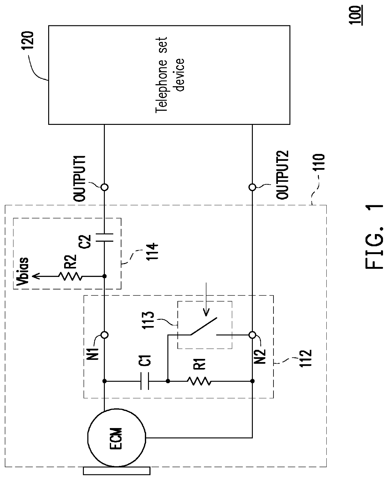
[0017]FIG. 1 is a schematic circuit diagram of a telephone device 100 according to the invention. The telephone device 100 includes a microphone device 110 and a telephone set device 120. The microphone device 110 mainly includes an audio source (for example, a microphone ECM) and a decoupling circuit 112. In addition, because the microphone ECM in the present embodiment is a single-ended input microphone, the microphone device 110 further includes a first resistor-capacitor circuit 114.
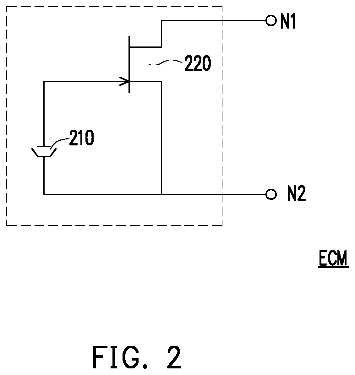
[0018]The microphone ECM includes a first terminal N1 and a second terminal N2. Because the microphone ECM in FIG. 1 of the present embodiment is a single-ended input microphone ECM, the first terminal N1 is an output terminal of the microphone ECM, and the second terminal N2 is a ground terminal of the microphone ECM. In an application of the present embodiment, the first terminal N1 may be considered as the ground terminal of the microphone ECM and the second terminal N2 may be considered as the ou...
second embodiment
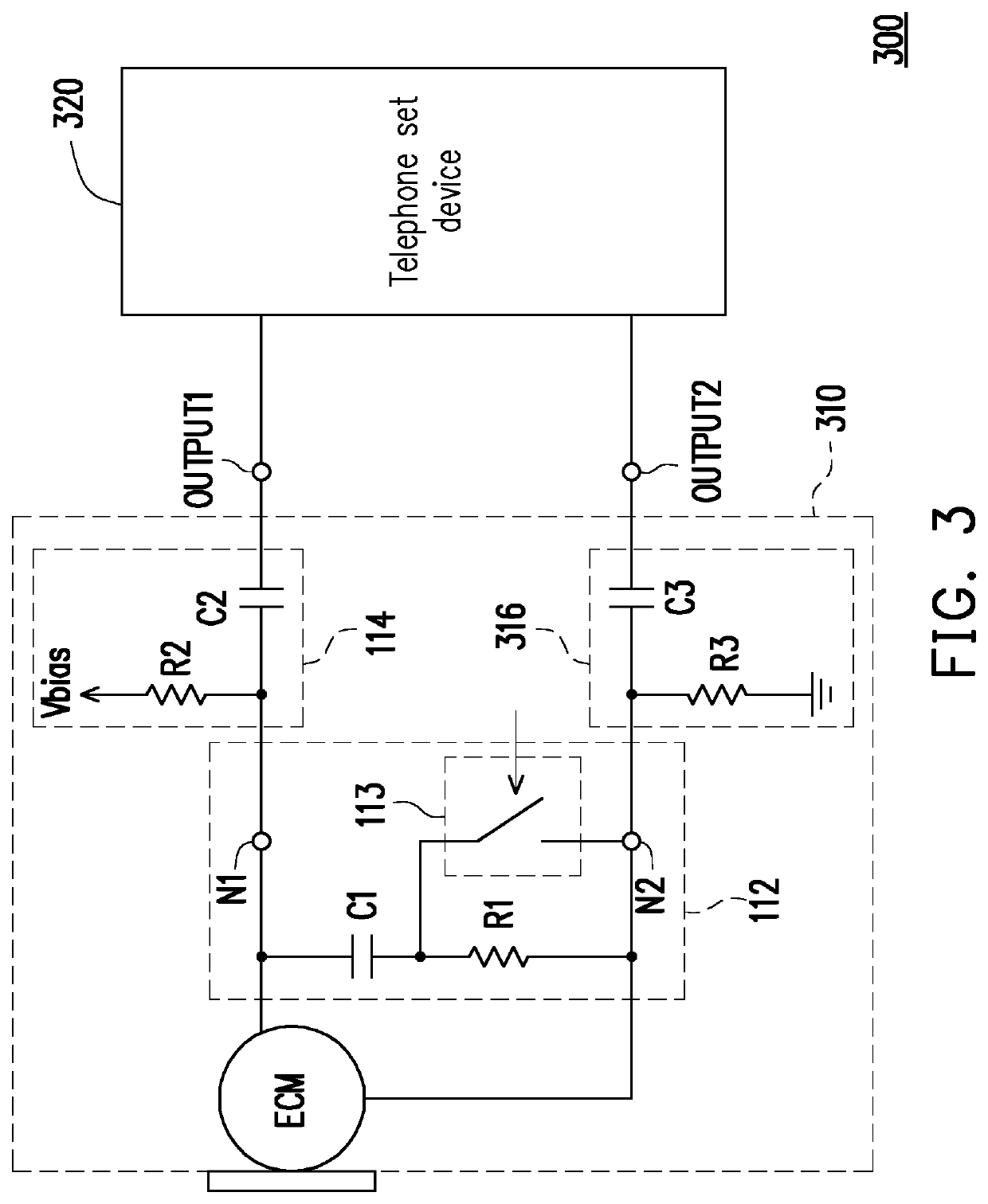
[0025]FIG. 3 is a schematic circuit diagram of a telephone device 300 according to the invention. A difference between the telephone device 300 in FIG. 3 and the telephone device 100 in FIG. 1 mainly lies in that, the telephone device 300 in FIG. 3 uses a differential input microphone ECM and a corresponding telephone set device 320. In an application of the present embodiment, any type of differential input microphone ECM may be used to implement the microphone ECM in FIG. 3. Therefore, in addition to the microphone ECM, the decoupling circuit 112, and the first resistor-capacitor circuit 114, the telephone device 300 in FIG. 3 further includes a second resistor-capacitor circuit 316. The first resistor-capacitor circuit 114 is coupled between a first terminal N1 of an audio source (the microphone ECM) and a first output terminal OUTPUT1 of a microphone device 310.
[0026]The second resistor-capacitor circuit 316 is coupled between a second terminal N2 of the audio source (the microp...
third embodiment
[0027]FIG. 4 is a schematic circuit diagram of a telephone device 400 according to the invention. The telephone device 400 in FIG. 4 includes a microphone device 410 and a telephone set device 120, and the microphone device 410 includes a microphone ECM, a decoupling circuit 412, and a first resistor-capacitor circuit 114. A difference between the telephone device 400 in FIG. 4 and the telephone device 100 in FIG. 1 mainly lies in that, a connection relationship between circuit components of the decoupling circuit 412 in the microphone device 410 in FIG. 4 is different from that of the decoupling circuit 112 in FIG. 1. A first terminal of a first capacitor C1 in the decoupling circuit 412 is coupled to a second terminal N2 of an audio source (the microphone ECM). A first terminal of a first resistor R1 is coupled to a second terminal of a first capacitor C1. A second terminal of the first resistor R1 is coupled to a first terminal N1 of the audio source (the microphone ECM). A first...
PUM
 Abstract
Description
Claims
Application Information
 - R&D
- Intellectual Property
- Life Sciences
- Materials
- Tech Scout
- Unparalleled Data Quality
- Higher Quality Content
- 60% Fewer Hallucinations
Browse by: Latest US Patents, China's latest patents, Technical Efficacy Thesaurus, Application Domain, Technology Topic, Popular Technical Reports.
© 2025 PatSnap. All rights reserved.Legal|Privacy policy|Modern Slavery Act Transparency Statement|Sitemap|About US| Contact US: help@patsnap.com


