
Method for setting a pitch angle of a rotor blade, control device for setting a pitch angle, and associated wind turbine

a technology of rotor blade and control device, which is applied in the direction of wind energy generation, mechanical equipment, machines/engines, etc., can solve the problems of only possible, inability to quickly adjust the pitch angle, and inability to achieve optimal conversion of wind power into electrical power, etc., to achieve the effect of high wind power efficiency

Active Publication Date: 2021-06-24
WOBBEN PROPERTIES GMBH
View PDF4 Cites 1 Cited by
  • Summary
  • Abstract
  • Description
  • Claims
  • Application Information

AI Technical Summary

Benefits of technology

The patent is about a method for setting the pitch angle of a wind turbine's rotor blades to improve efficiency, particularly at low air densities. The method takes into account the aerodynamic power instead of electrical power, which allows for steeper patch angle gradients, which in turn leads to better efficiency and faster reactions to changes in wind speed. The use of aerodynamic power also allows for a greater reaction of the pitch drive without reaching the stability limits of the control system. The method takes into account the difference between the established pitch angle and the set pitch angle value to avoid unnecessary operation and wear on the wind turbine. The patent also describes a control device and a wind turbine that use this method.

Problems solved by technology

Such a rapid adjustment of the pitch angle is not however possible, or only possible within restrictions, with the control technology currently used.
Inter alia, this leads to a restricted power capacity of the wind turbine which in particular results in a non-optimal conversion of the wind into electrical power.

Method used


Image

  • Method for setting a pitch angle of a rotor blade, control device for setting a pitch angle, and associated wind turbine
  • Method for setting a pitch angle of a rotor blade, control device for setting a pitch angle, and associated wind turbine
  • Method for setting a pitch angle of a rotor blade, control device for setting a pitch angle, and associated wind turbine

Examples


Embodiment Construction

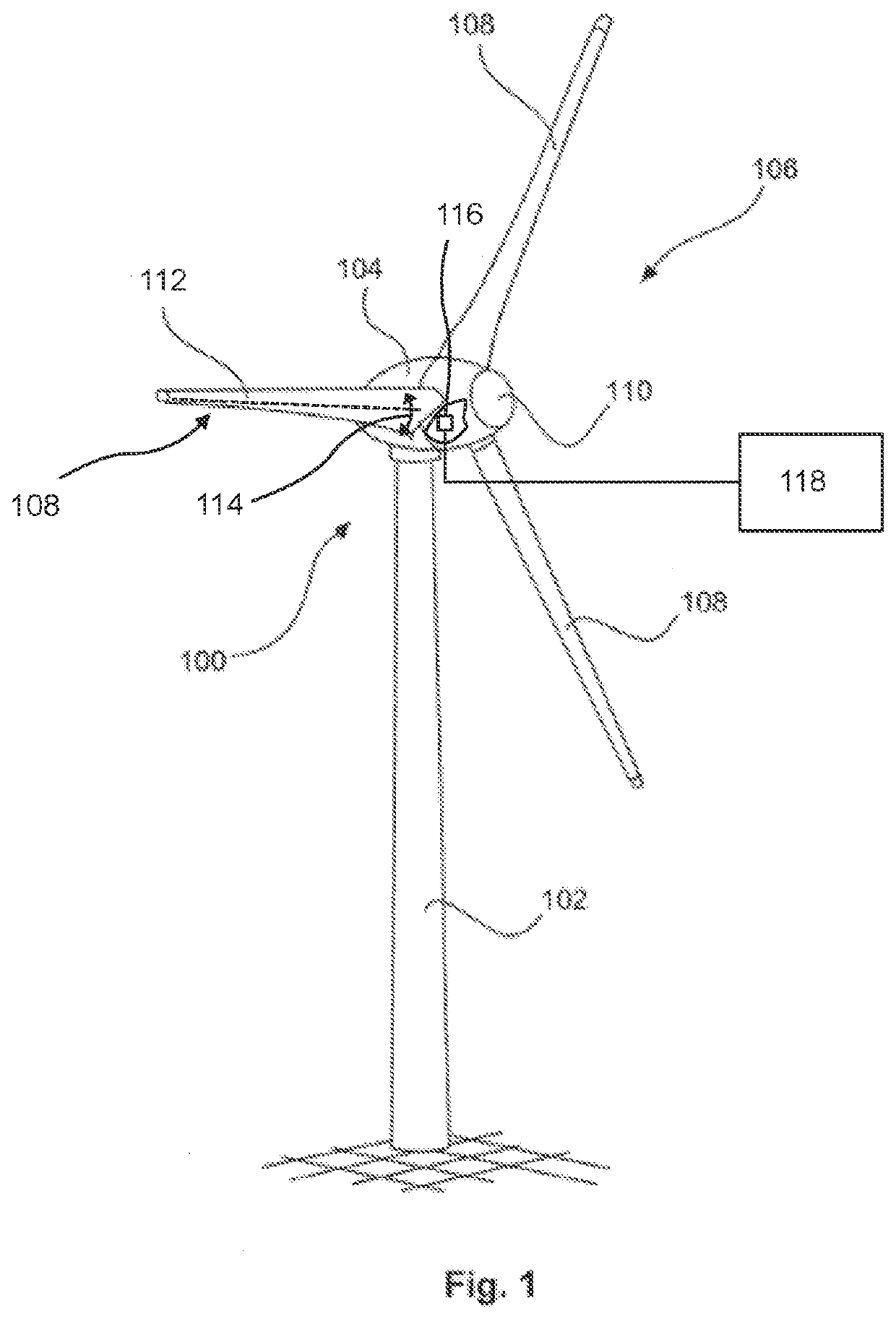
[0066]FIG. 1 shows a diagrammatic, three-dimensional view of a wind turbine 100. The wind turbine 100 has a tower 102 and a nacelle 104 on the tower 102. An aerodynamic rotor 106 with three rotor blades 108, each having a rotor blade length, and a spinner 110 are provided on the nacelle 104. The aerodynamic rotor 106 is set in rotational movement by the wind during operation of the wind turbine 100 and thus also turns an electrodynamic rotor of a generator which is coupled directly or indirectly to the aerodynamic rotor 106. The electrical generator is arranged in the nacelle 104 and generates electrical energy.

[0067]The rotor blades 108 each have a rotor blade longitudinal axis 112. The rotor blade longitudinal axis 112 extends substantially from a root region of the rotor blade facing the nacelle 104 to a rotor blade tip facing away from the nacelle 104. The rotor blades 108 are arranged so as to be rotationally movable around the rotor blade longitudinal axis 112. In particular, ...


PUM


Abstract

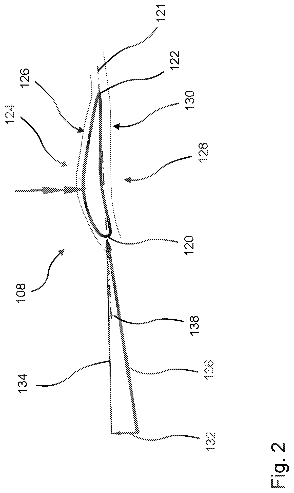
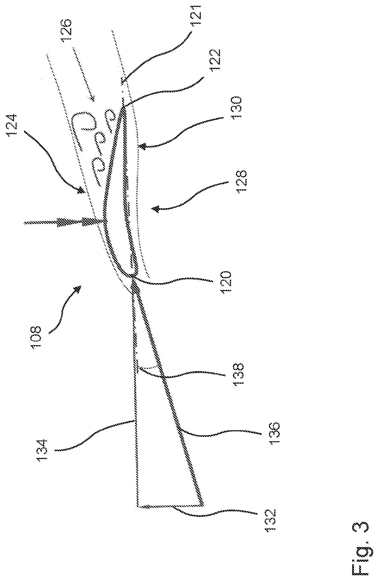
A method for setting a pitch angle of a rotor blade for a rotor of a wind turbine, a control device for setting a pitch angle of a rotor blade for a rotor of a wind turbine, and a wind turbine. In particular, a method for setting a pitch angle of a rotor blade for a rotor of a wind turbine, in particular for avoiding suction-side flow separation, wherein the rotor blade is movable rotationally about a rotor blade longitudinal axis for setting the pitch angle by means of a pitch drive, comprising the steps: determining an aerodynamic power of the rotor, establishing a nominal pitch angle as a function of the aerodynamic power, and setting the pitch angle to the established nominal pitch angle.

Description

BACKGROUNDTechnical Field[0001]The disclosure concerns a method for setting a pitch angle of a rotor blade for a rotor of a wind turbine, a control device for setting a pitch angle of a rotor blade for a rotor of a wind turbine, and a wind turbine.DESCRIPTION OF THE RELATED ART[0002]Wind turbines are known in principle and generate electrical power from wind. Modern wind turbines are usually so-called horizontal axis wind turbines in which the rotor axis is arranged substantially horizontally and the rotor blades sweep a substantially vertical rotor field. Wind turbines also usually comprise, as well as a rotor arranged on a nacelle, a tower on which the nacelle with the rotor is arranged so as to be rotatable about an axis oriented substantially vertically. The rotor usually comprises one, two or more rotor blades of equal length. The rotor blades are slender components which are often made from fiber-reinforced plastic.[0003]The rotor blades usually have a rotor blade longitudinal...

Claims


Application Information

Patent Timeline
Patent Type & Authority Applications(United States)
IPC IPC(8): F03D7/02F03D7/04
CPCF03D7/0224F03D7/042F05B2270/328F05B2270/327F05B2270/32F05B2270/331F03D17/00F03D7/0276F05B2270/309Y02E10/72
Inventor SCHAPER, ULF
Owner WOBBEN PROPERTIES GMBH
Learn More