Electric cable for a wind turbine and wind turbine

a technology for wind turbines and electric cables, which is applied in the direction of cables, insulated conductors, conductors, etc., can solve the problems of difficult cooling requirements of cables and inability to ensure efficient cooling of cables

Active Publication Date: 2020-11-12
SIEMENS GAMESA RENEWABLE ENERGY AS
View PDF3 Cites 0 Cited by
  • Summary
  • Abstract
  • Description
  • Claims
  • Application Information

AI Technical Summary

Benefits of technology

[0006]The cooling element acts as a means for transferring heat from the cable to the air in the vicinity of the cable. The cooling element increases the surface area of the cable being in contact with the air which leads to a higher efficiency of the heat transfer from the region of the cable, where the heat is typically produced in, e.g. a conductor or a wire, to the air. In addition, since the cooling element protrudes from the surface of the electric cable, the movement of air passing by the cable is affected by the cooling element, e.g. leading to turbulences or swirls of the air in the vicinity of the cable, which also enhance the heat transfer from the cable to the air.
[0007]Both effects, the increase of the surface area of the cable and the creation of turbulences of the air passing by the cable lead to an improved cooling rate or cooling capacity of the cables. In other words, the amount of heat which can be removed from the cable within a certain time span and under certain temperature conditions is increased. As a consequence, a sufficient cooling can be ensured even at weather conditions with high air temperatures. Furthermore, the upper limit of the power production rate of the wind turbine caused by the heat generated by the cables is raised leading to a higher efficiency of the wind turbine.
[0008]In a preferred embodiment of the invention, the cooling element is a fin. Fins typically comprise an elongated and plate-like or, in other words, flat structure. Especially if a plurality of fins are provided, the surface of the electric cable interacting with the air passing by the cable can be increased using with less additional material. Thus, a lightweight construction as well as low additional material costs of the cable are possible.
[0013]Due to the wound geometrical shape of the helical fin, turbulences or swirls of the air passing by the electric cable are induced even more efficiently and, hence, the cooling rate is improved. The geometrical properties of the helical fin, in particular its dimension and / or shape and / or the gradient of the windings, i.e. the angle between the fin and the longitudinal axis of the electric cable, can be chosen as certain values to realize a desired cooling rate.
[0014]In an embodiment of the invention, the at least one cooling element can be part of or can be attached to a metallic sheath of the electric cable. The cooling element is preferably a fin protruding from the anti-corrosion sheath of the electric cable. The electric cable can be multi-layered, i.e. it can be a coaxial cable or the like. In this embodiment, preferably a conductor of the cable is located in the axial centre of the electric cable and covered by a conductor screen. Radially outwards, the conductor screen can be covered by an insulation layer, which might consist of a dielectric material like plastics or the like. Going radially further outwards, an insulation screen is provided which is covered by the metallic sheath. The metallic sheath reduces potential electromagnetic interferences between the cable and other electrical devices located in the vicinity of the cable. The outermost layer of the shielded cable can be an anti-corrosion sheath preventing the cable from humidity, radiation or other unwanted influences from the outside. Since the metallic sheath typically comprises a comparably high thermal conductivity, the cooling efficiency is improved if the cooling element is part of or being in thermal contact with the metallic sheath. The cooling element can be exposed or, at least partially, covered by the anti-corrosion sheath.
[0018]The wind turbine preferably comprises at least two openings to enable air to enter and to leave the interior of the wind turbine, in particular the tower. Exemplarily, air filters can be provided on the openings preventing air contaminated by dust or other pollution from entering the wind turbine. Preferably, at least one of the openings is located in a lower part of the wind turbine like on the bottom of the tower, and at least one of the other openings is located on an upper part of the wind turbine, especially on the top of the tower or the roof or canopy of the nacelle. The cooling of the cables can be realized by ambient air entering one of the openings of the wind turbine and leaving the wind turbine through another opening, realising an airflow through the wind turbine cooling the electric cables.

Problems solved by technology

The cooling requirements of the cables become quite challenging in extreme weather conditions, e.g. when the temperature of the ambient air is a relatively high.
In particular, when the temperature of the ambient air is around 45° C. or higher, an efficient cooling of the cables cannot be ensured.

Method used


Image

  • Electric cable for a wind turbine and wind turbine
  • Electric cable for a wind turbine and wind turbine
  • Electric cable for a wind turbine and wind turbine

Examples


first embodiment

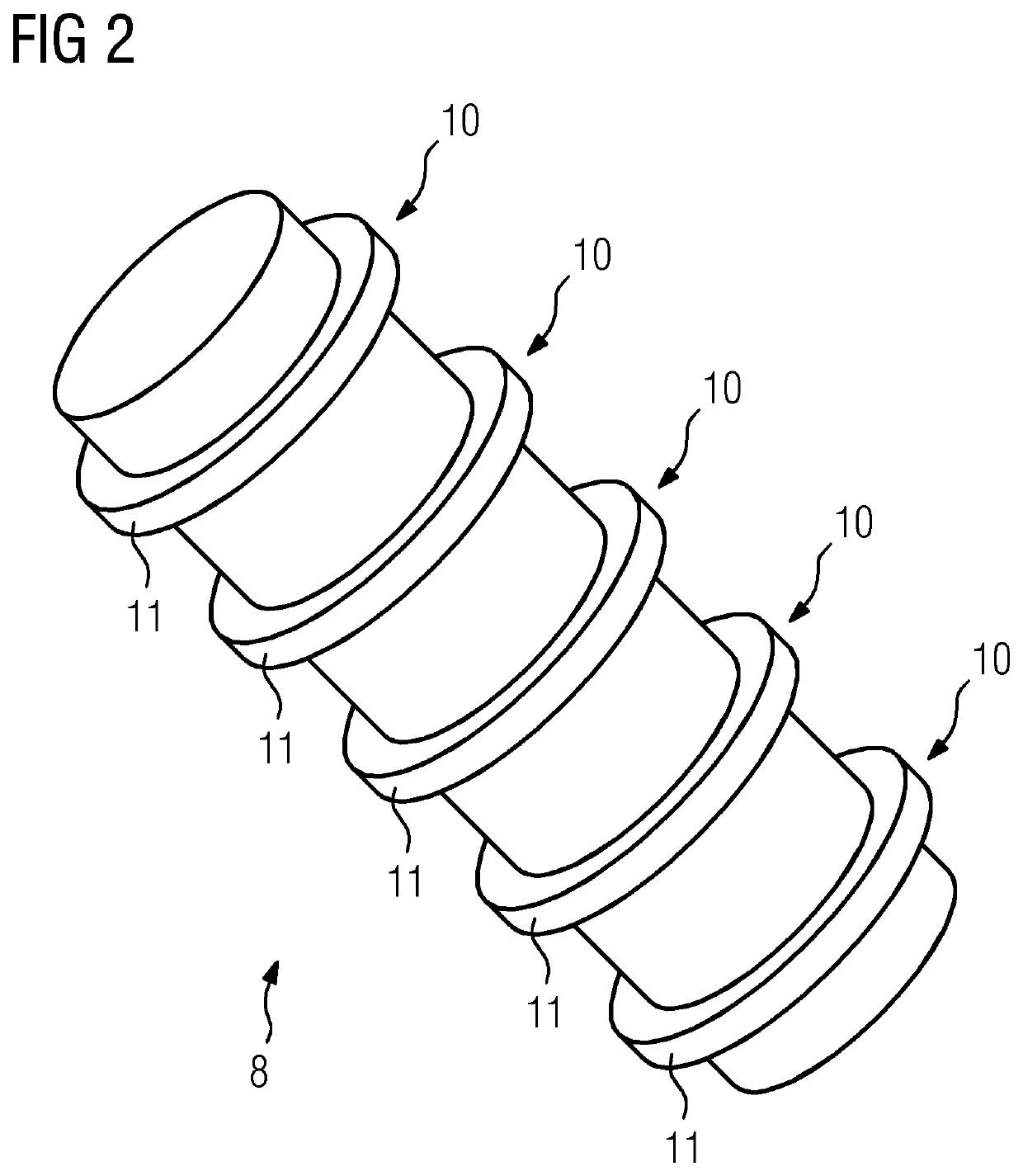
[0031]FIG. 2 shows a detailed view of the electric cable 8. Here, the cooling elements 10 are annular fins 11 extending along the circumference of the electric cable 8. The cross-sectional shape of each of the annular fins 11 is rectangular, meaning that the geometrical shape of each of the annular fins 11 is a ring or hollow cylinder of low height. Exemplarily, the height of the hollow cylinders forming the annular fins 11 is about 1 mm and the distance between two adjacent annular fins is about 10 mm.

second embodiment

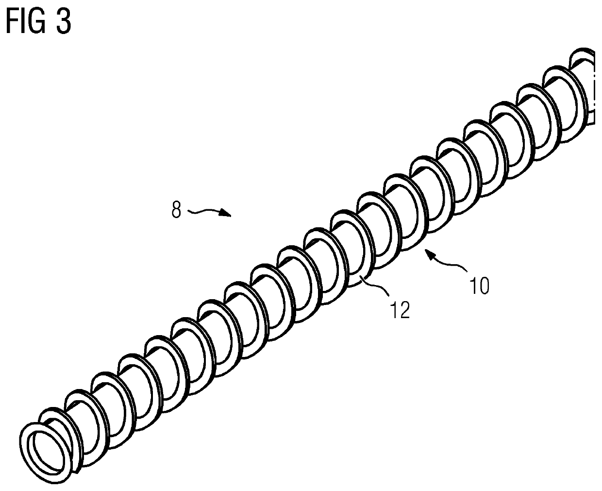
[0032]FIG. 3 shows the electric cable 8, wherein the cooling element 10 is provided as a helical, circumferential fin 12 along the periphery of the electric cable 8. Exemplarily, the helical, circumferential fin 12 extends along the cable 8 continuously. Alternatively, several separate helical fins 12 can be provided each covering a certain longitudinal section of the electric cable 8. Even two or more parallel helical fins 12 can extend along the periphery of the electric cable 8, e.g. forming a double- or multiple helical structure.

[0033]Due to the twisted shape of the helical, circumferential fin 12, the cooling element 10 produces or increases turbulences and swirls of the air passing by the cable 8 which lead to an even higher cooling efficiency. Exemplarily, the gradient of the twisted structure of the helical, circumferential fin 12 is chosen such that at a length of 20 cm of the cable 8, the helical, circumferential fin 12 twists eight times around the cable 8.

[0034]FIG. 4 s...


PUM


Abstract

Provided is an electric cable for a wind turbine, wherein the electric cable includes at least one cooling element) to cool the electric cable, wherein the cooling element protrudes from the surface of the electric cable.

Description

CROSS-REFERENCE TO RELATED APPLICATIONS[0001]This application claims priority to European Application No. 19173576.0, having a filing date of May 9, 2019, the entire contents of which are hereby incorporated by reference.FIELD OF TECHNOLOGY[0002]The following relates to an electric cable for a wind turbine.BACKGROUND[0003]Since electric cables of wind turbines typically carry high currents, heat is generated by the wires or conductors of these cables. As a consequence, the cables have to be cooled, e.g. by convection of air passing by the cable, by a draft flow in the tower or the like. Additionally, a tower fan can be provided producing a forced flow of, in particular ambient, air through the tower and cooling the cables. The cooling requirements of the cables become quite challenging in extreme weather conditions, e.g. when the temperature of the ambient air is a relatively high. In particular, when the temperature of the ambient air is around 45° C. or higher, an efficient coolin...

Claims


Application Information

Patent Timeline
Patent Type & Authority Applications(United States)
IPC IPC(8): F03D80/80H02K7/18
CPCF03D80/85H02K7/1838F03D80/00F03D80/60H01B7/426H02G3/03F05B2260/20Y02E10/72H01B7/184H01B7/1875
Inventor RAFIEEARASHTNAB, MAHSA
Owner SIEMENS GAMESA RENEWABLE ENERGY AS
Why Eureka
Try Eureka