A wind wheel for motor heat dissipation and a fan including the wind wheel

A technology of motor heat dissipation and wind wheel, which is applied to machines/engines, parts of pumping devices for elastic fluids, mechanical equipment, etc., which can solve problems such as inability to dissipate heat from the motor, reduced motor efficiency, and failure of electronic control, etc., to achieve a solution The effect of low motor efficiency, avoiding excessive temperature rise, and improving service life

Active Publication Date: 2020-11-06
FANS TECH ELECTRIC CO LTD
View PDF8 Cites 0 Cited by
  • Summary
  • Abstract
  • Description
  • Claims
  • Application Information

AI Technical Summary

Problems solved by technology

[0003] 1. The heat dissipation of the motor is slow, resulting in a decrease in the efficiency of the motor
[0004] 2. The high temperature causes the life of the bearing inside the motor to decrease, and in severe cases, it is easy to cause the bearing to be stuck
[0005] 3. For brushless motors, if they are used in a high temperature environment, such as poor heat dissipation, it is easy to cause the temperature rise of the electric control part of the motor to be too high, resulting in the failure of the electric control
In this patent, there is a reinforcement plate between the connecting ring and the inner ring in the fan blade structure. The reinforcement board structure cannot dissipate heat to the motor, and the use of the fan blade structure in high temperature environments has certain limitations.

Method used


Image

  • A wind wheel for motor heat dissipation and a fan including the wind wheel
  • A wind wheel for motor heat dissipation and a fan including the wind wheel
  • A wind wheel for motor heat dissipation and a fan including the wind wheel

Examples


Embodiment 1

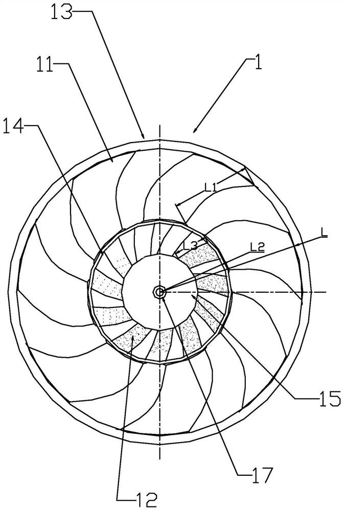
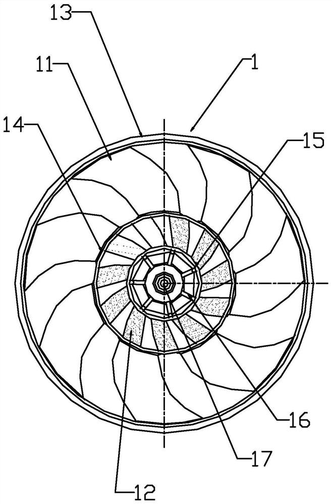
[0041] Such as figure 1 and 2 As shown, this embodiment discloses a wind wheel for motor heat dissipation, including a wind wheel hub 15, an inner wind guide ring 14, an outer wind guide ring 13, and a wind wheel hub 15 arranged on the inner wind guide ring 14 and the wind wheel hub 15. The inner blades 12 between them, the outer blades 11 arranged between the inner wind guide ring 14 and the outer wind guide ring 13, the inner blades 12 and the outer blades 11 are all based on the The central axis of the wind rotor hub 15 is the center of rotation, and the bending directions of the inner blades 12 and the outer blades 11 are the same. The blade root of the inner blade 12 is connected to the outer wall of the wind rotor hub 15, the blade tip of the inner blade 12 is connected to the inner wall of the inner wind guide ring 14, and the blade root of the outer blade 11 is connected to the inner wind guide ring. The outer wall of the ring 14 is connected, and the tip of the oute...

Embodiment 2

[0051] This embodiment only describes the difference from the above embodiment, and other technical features are the same as the above embodiment. In this embodiment, the relationship between the radius L of the wind wheel 1, the length L1 of the outer blade 11, the radius L2 of the inner circle of the inner wind guiding ring 14, and the length L3 of the inner blade 12 is: 0.2 L≦L1≦0.4L, 0.2L2≦L3≦0.4L2. Such setting is to ensure a sufficient ventilation system of the wind rotor 1 and excessive heat dissipation channels will affect the air volume of the wind rotor 1 .

Embodiment 3

[0053] This embodiment only describes the difference from the above embodiment, and other technical features are the same as the above embodiment. In this embodiment, the number of the outer blades 11 and the inner blades 12 are not in multiples, otherwise the fundamental and harmonic noise generated by the rotation of the outer blades 11 and the inner blades 12 will be superimposed, so that Wind wheel 1 produces abnormal noise.


PUM


Abstract

The invention discloses a wind wheel for motor heat dissipation and a fan comprising the wind wheel. The wind wheel comprises a wind wheel hub, an inner wind guiding ring, an outer wind guiding ring,inner-layer blades arranged between the inner wind guiding ring and the wind wheel hub, and outer-layer blades arranged between the inner wind guiding ring and the outer wind guiding ring. A central axis of the wind wheel hub serves as a rotating center of the inner-layer blades and the outer-layer blades, and the inner-layer blades and the outer-layer blades are the same in bent direction. The fan comprises a motor, the wind wheel and a fan support, wherein the motor comprises a front end cover and a rear end cover, the inner-layer blades in the fan and cooling fins on the outer side of the motor are used in cooperation to enable a heat dissipation flow channel formed by the inner-layer blades of the wind wheel to dissipate heat of the motor, and meanwhile, the outer-layer blades are matched with the fan support to form a ventilation flow channel to achieve wind output of the fan, and the ventilation flow channel and the heat dissipation flow channel do not interfere with each other.

Description

technical field [0001] The invention relates to the field of fans, in particular to a wind wheel for motor heat dissipation and a fan including the wind wheel. Background technique [0002] Due to the limitation of the space size of the existing fans, the motors are generally placed inside the hub of the wind wheel, which easily leads to slow heat dissipation of the motor and overheating of the motor. Especially when the fan is used in a high temperature environment, there are mainly the following three problems: [0003] 1. The heat dissipation of the motor is slow, resulting in a decrease in the efficiency of the motor. [0004] 2. The high temperature causes the life of the bearing inside the motor to decrease, and in severe cases, it is easy to cause the bearing to be stuck. [0005] 3. For the brushless motor, if it is used in a high temperature environment, such as poor heat dissipation, it is easy to cause the temperature rise of the electric control part of the mot...

Claims


Application Information

Patent Timeline
Patent Type & Authority Patents(China)
IPC IPC(8): F04D29/28F04D29/30F04D29/58H02K9/06
CPCF04D29/281F04D29/30F04D29/5806F04D29/5853H02K9/06
Inventor 陈国栋莫远忠黄鑫城
Owner FANS TECH ELECTRIC CO LTD
Why Eureka
Try Eureka