UV curing machine

A technology of curing machine and shell, which is applied in the direction of pretreatment surface, coating, device for coating liquid on the surface, etc., can solve the problems of uneven heating of products, shortened UV life, etc., to improve production efficiency and product quality, Extend life and enhance the effect of irradiation energy

Inactive Publication Date: 2015-02-18
SUZHOU AISITE IND EQUIP
View PDF4 Cites 8 Cited by
  • Summary
  • Abstract
  • Description
  • Claims
  • Application Information

AI Technical Summary

Problems solved by technology

It has the characteristics of environmental protection, safety, fast speed and good compatibility, so it has been widely used, but because the UV light temperature is too high, it is easy to cause uneven heating of the product, and the UV life will be greatly shortened

Method used


Image

  • UV curing machine
  • UV curing machine

Examples


Embodiment 1

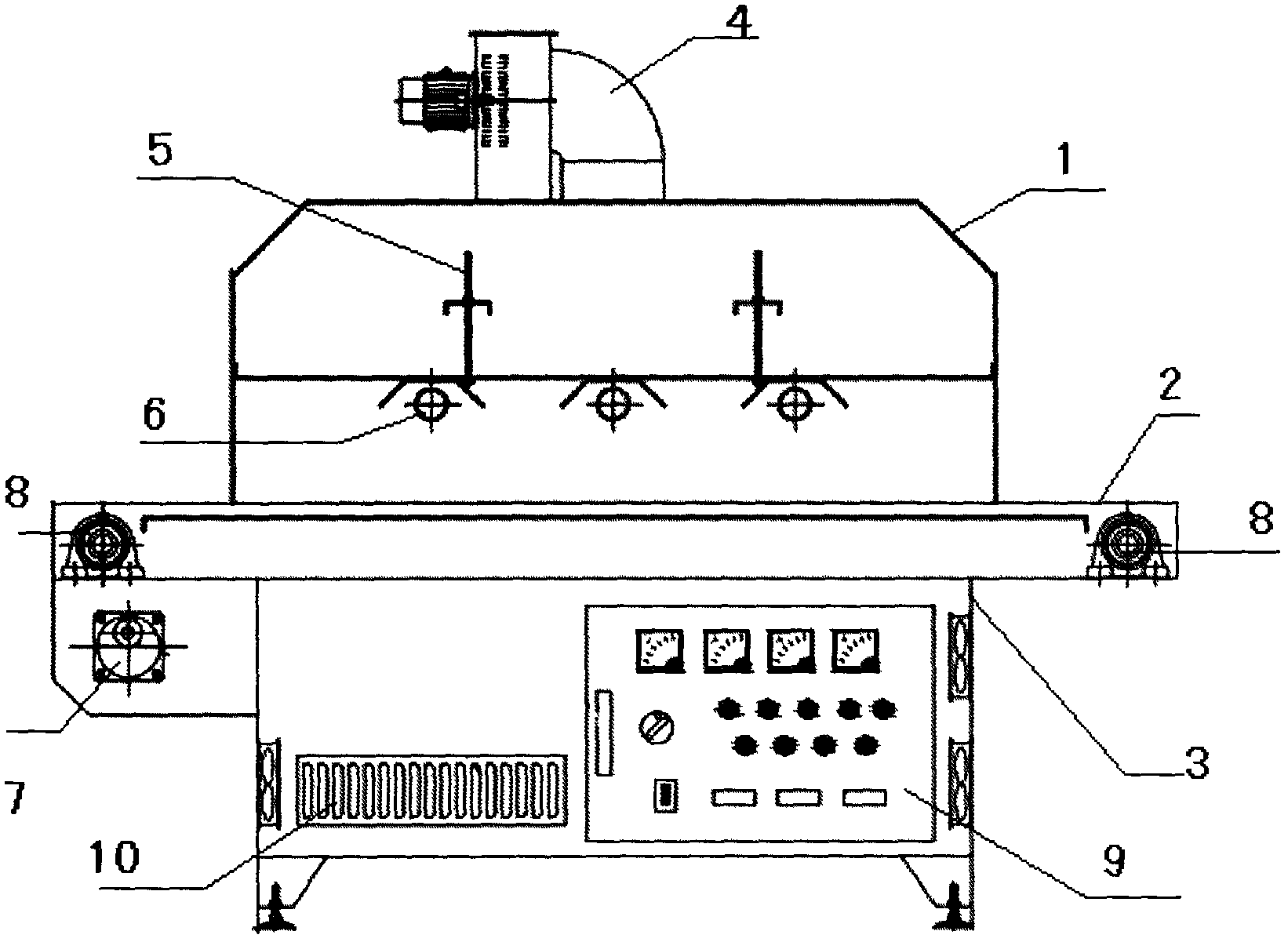
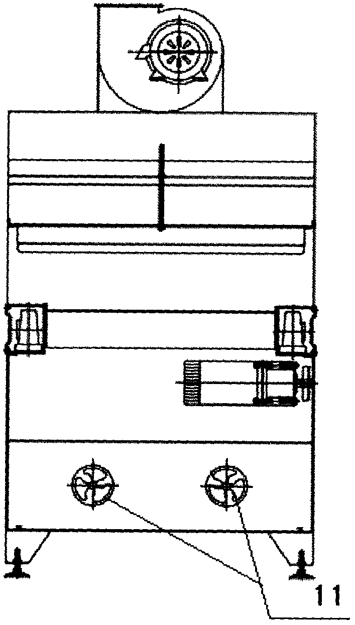
[0018] combined with figure 1 and attached figure 2 As shown, the present embodiment provides a UV curing machine, including a housing 1, which is a hollow box structure, and the bottom of both ends of the housing are respectively provided with a feed port and a discharge port, and the top of the housing is provided with The exhaust fan 4 is suspended with a UV lamp 6 fixed on the lamp stand in the middle of the housing, and the lamp stand is fixed on the bracket above the lamp stand through an adjusting screw 5; the transmission table 2 is located at the Below the UV lamp, one end of the conveyor belt is connected to the feed port, and one end is connected to the discharge port, and a roller 8 is respectively arranged on the conveyor table at the feed port and the discharge port; the console 3. Located below the transmission platform, the console 3 is a hollow steel structure without a top, and the surrounding steel plates are welded to the transmission platform 2. The cont...

Embodiment 2

[0020] combined with figure 1 and attached figure 2 As shown, the present embodiment provides a UV curing machine, including a housing 1, which is a hollow box structure, and the bottom of both ends of the housing are respectively provided with a feed port and a discharge port, and the top of the housing is provided with The exhaust fan 4 is suspended with a UV lamp 6 fixed on the lamp stand in the middle of the housing, and the lamp stand is fixed on the bracket above the lamp stand through an adjusting screw 5; the transmission table 2 is located at the Below the UV lamp, one end of the conveyor belt is connected to the feed port, and one end is connected to the discharge port, and a roller 8 is respectively arranged on the conveyor table at the feed port and the discharge port; the console 3. Located below the transmission platform, the console 3 is a hollow steel structure without a top, and the surrounding steel plates are welded to the transmission platform 2. The cont...


PUM


Abstract

The invention discloses a UV (ultraviolet) curing machine which comprises a shell (1), a conveying table (2) and a control console (3), wherein the shell (1) is of a hollow box body structure, wherein a material inlet and a material outlet are respectively formed in the bottoms of two ends of the shell; an exhaust fan (4) is arranged at the top of the shell; UV lamps (6) fixed on a lamp support are suspended in the middle of the interior of the shell; the lamp support is fixed on a bracket above the lamp support through adjustment screw rods (5); the conveying table (2) is positioned below the UV lamp; one end of a conveying belt is connected with the material inlet, and the other end of the conveying belt is connected with the material outlet; a rotary drum (8) is arranged on the conveying table at each of the material inlet and the material outlet; the control console (3) is positioned below the conveying table and is of a topless square hollow steel structure; peripheral steel plates are welded with the conveying table (2); a control panel (9) is fixed on the steel plate on one side of the control console; heat dissipation holes (10) are formed close to the bottom of the control console; a speed reduction motor (7) is arranged close to the material inlet and is connected with the rotary drum (8) at the material inlet through the conveying belt.

Description

technical field [0001] The invention relates to a curing device, in particular to a UV curing machine. Background technique [0002] At present, when many enterprises produce and process products, they need to use various UV glues for glue dropping and fixing, and then cure the UV glues in time. UV glue, also known as shadowless glue, photosensitive glue, and ultraviolet light curing glue, refers to a type of adhesive that must be cured by ultraviolet light. It can be used as an adhesive or as a glue for paints, coatings, inks, etc. Material use. The principle of UV glue curing is that the photoinitiator (or photosensitizer) in the UV curing material absorbs ultraviolet light under the irradiation of ultraviolet rays to generate active free radicals or cations, triggering chemical reactions of monomer polymerization, crosslinking and grafting, so that the adhesion The agent changes from liquid to solid within seconds. It has the characteristics of environmental protection...

Claims


Application Information

Patent Timeline
Patent Type & Authority Applications(China)
IPC IPC(8): B05D3/06
Inventor 胡路
Owner SUZHOU AISITE IND EQUIP
Why Eureka
Try Eureka