
Wing-Shaped Thrust Screw

Inactive Publication Date: 2021-06-24
CHEN WEI CHIH
View PDF0 Cites 0 Cited by
  • Summary
  • Abstract
  • Description
  • Claims
  • Application Information

AI Technical Summary

Benefits of technology

The present invention provides a thrust screw that is integrally formed with the thrust member, preventing the external thread from being screwed or locked too deep due to defects or improper operation. This helps prevent the thrust screw from breaking or wearing out during rotation. The invention also includes a thrust screw that improves the efficiency and performance of screwing operations.

Problems solved by technology

However, the wall anchor and the headless screw are not formed integrally, and have a complicated working process, thereby increasing the cost of fabrication.
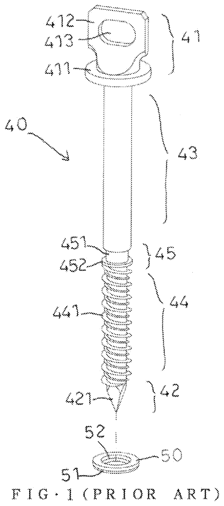
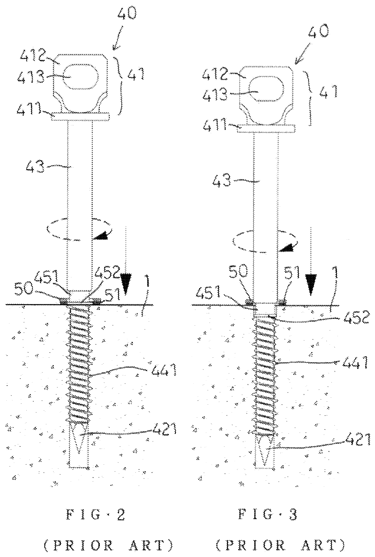
The two enlarged portions do not have a thrust function and cannot prevent a further screwing motion of the external thread.
However, the two convex fin portions do not have a thrust function, and cannot stop a further screwing motion of the thread section.

Method used


Image

  • Wing-Shaped Thrust Screw
  • Wing-Shaped Thrust Screw
  • Wing-Shaped Thrust Screw

Examples


Embodiment Construction

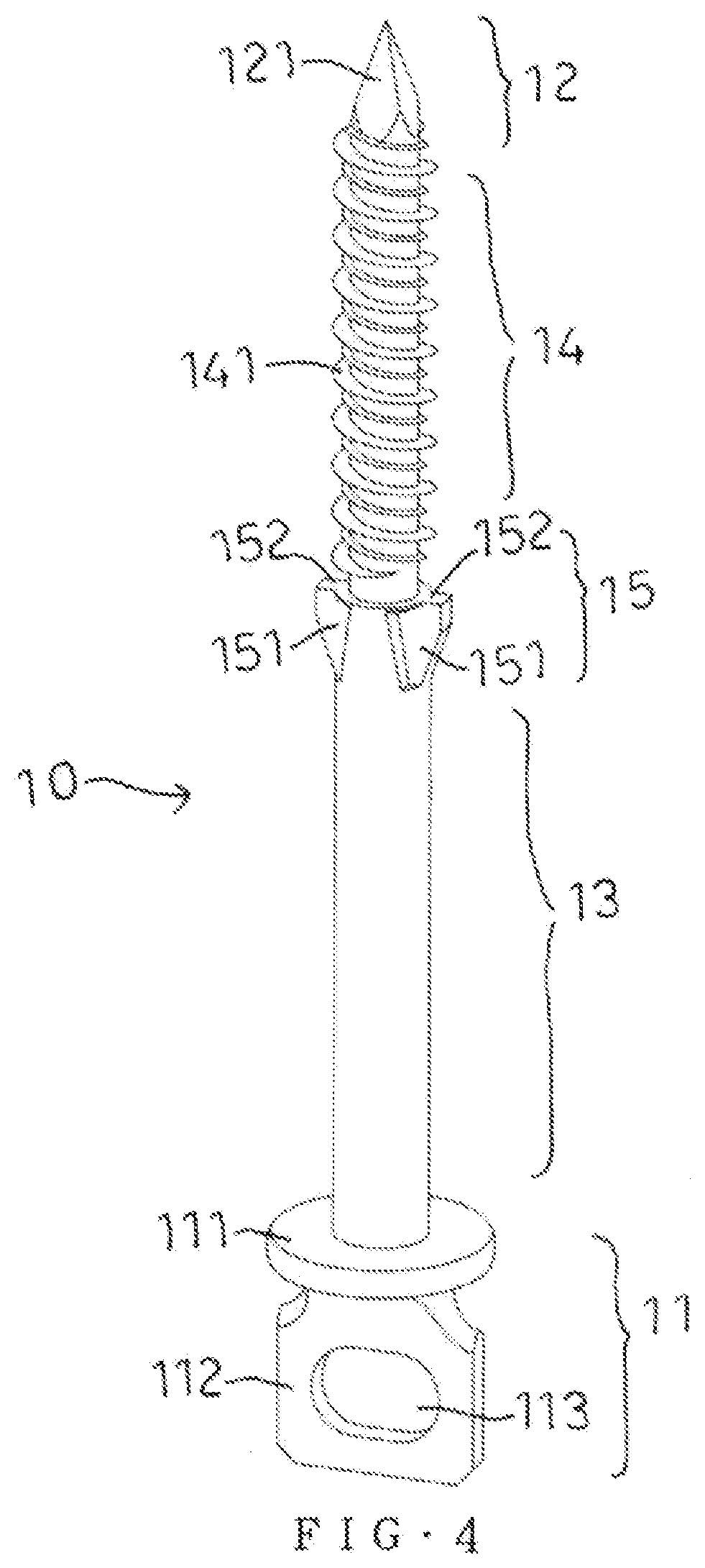
[0025]Referring to the drawings and initially to FIGS. 4-6, a thrust screw 10 in accordance with the preferred embodiment of the present invention comprises a head 11, a first shank 13, a second shank 14, and a drilling member 12.

[0026]The first shank 13 and the second shank 14 are arranged between the head 11 and the drilling member 12. The second shank 14 is provided with an external thread 141. The first shank 13 is provided with a thrust member (or stop member) 15 corresponding to the external thread 141. The thrust member 15 is connected with the external thread 141 of the second shank 14 and includes two wing-shaped (or fin-shaped) stop pieces 151 and two flat portions 152. The two wing-shaped stop pieces 151 are formed on and protrude outward from the first shank 13. The two flat portions 152 are formed on the two wing-shaped stop pieces 151 respectively and correspond to the external thread 141. The two flat portions 152 have an outer diameter (or a dimension) greater than t...


PUM

PropertyMeasurementUnit
Diameteraaaaaaaaaa

Abstract

A thrust screw includes a head, a first shank, a second shank, and a drilling member. The first shank and the second shank are arranged between the head and the drilling member. The second shank is provided with an external thread. The first shank is provided with a thrust member corresponding to the external thread. The thrust member includes two wing-shaped stop pieces and two flat portions. The two flat portions are formed on the two wing-shaped stop pieces respectively and correspond to the external thread. The two flat portions have an outer diameter greater than that of the external thread. The two flat portions of the thrust member stop a further screwing motion of the external thread.

Description

BACKGROUND OF THE INVENTION1. Field of the Invention[0001]The present invention relates to a screw and, more particularly, to a wing-shaped thrust screw (or self-tapping screw).2. Description of the Related Art[0002]A conventional anchor for masonry veneer walls was disclosed in the U.S. Pat. No. 4,764,069. The tail end of the wall anchor is provided with an internally threaded hole for locking a headless screw, so that the headless screw can be locked and fixed in the internally threaded hole of the wall anchor. The headless screw has a tail provided with a drill tip. The outer diameter of the tail end of the wall anchor is larger than that of the thread of the headless screw, thereby forming a thrust part to prevent a further screwing motion of the headless screw. The wall anchor and the headless screw are produced individually. The wall anchor and the headless screw are made the zinc alloy which is cast and then tapped to form the thread, and finally the headless screw is locked ...

Claims


Application Information

Patent Timeline
IPC IPC(8): F16B25/10F16B25/00
CPCF16B25/103F16B25/0084F16B25/0063F16B25/0015F16B25/0089F16B25/0026F16B43/00F16B45/002
Inventor CHEN, WEI-CHIH
Owner CHEN WEI CHIH
Learn More