Gas control device and gas control method
- Summary
- Abstract
- Description
- Claims
- Application Information
AI Technical Summary
Benefits of technology
Problems solved by technology
Method used
Image
Examples
first embodiment
1. First Embodiment
[1.1. Vehicle 10]
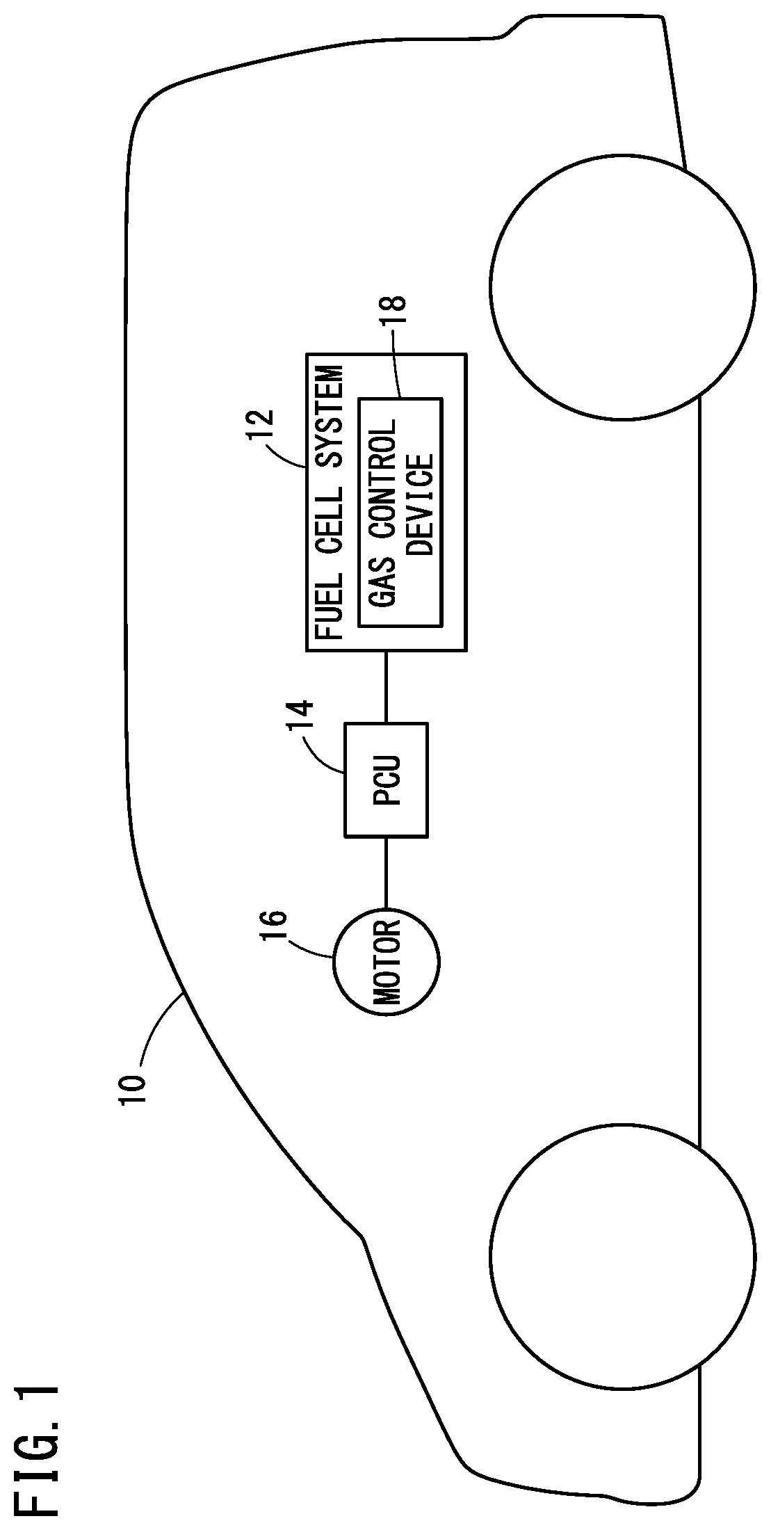
[0035]As shown in FIG. 1, the embodiment described below assumes a gas control device 18 that is provided in a fuel cell system 12 of a vehicle 10. The vehicle 10 is a fuel cell vehicle and includes the fuel cell system 12, a PCU (Power Control Unit) 14, and a drive motor 16 as the load. The fuel cell system 12 includes the gas control device 18 and generates electric power through electrochemical reactions between hydrogen and oxygen. The PCU 14 includes a DC / DC converter and inverter (neither of which is shown). The PCU 14 controls the output from the fuel cell system 12 and outputs it to the motor 16 in response to a command signal from a drive ECU (not shown) configured to control the drive system of the vehicle 10. The motor 16 generates driving power for the vehicle 10.
[1.2. Configuration of Gas Control Device 18]
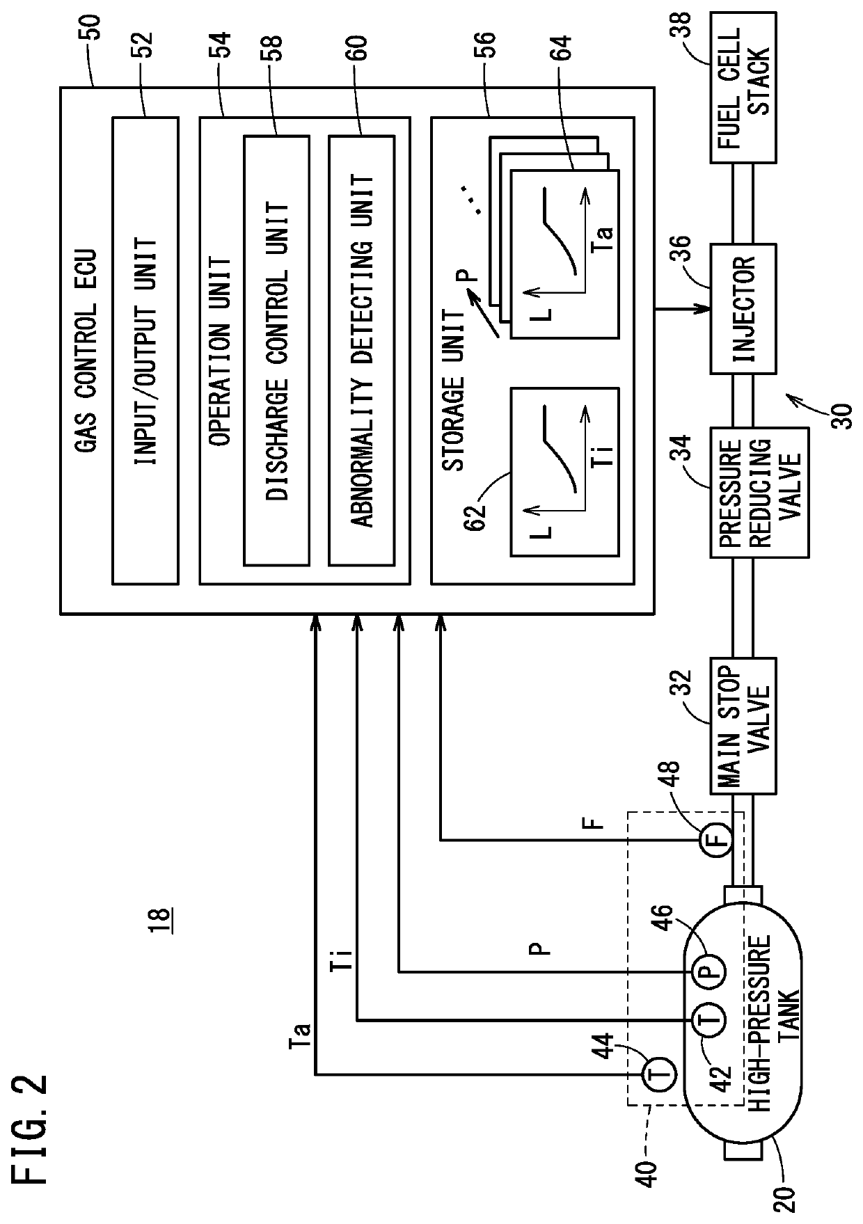
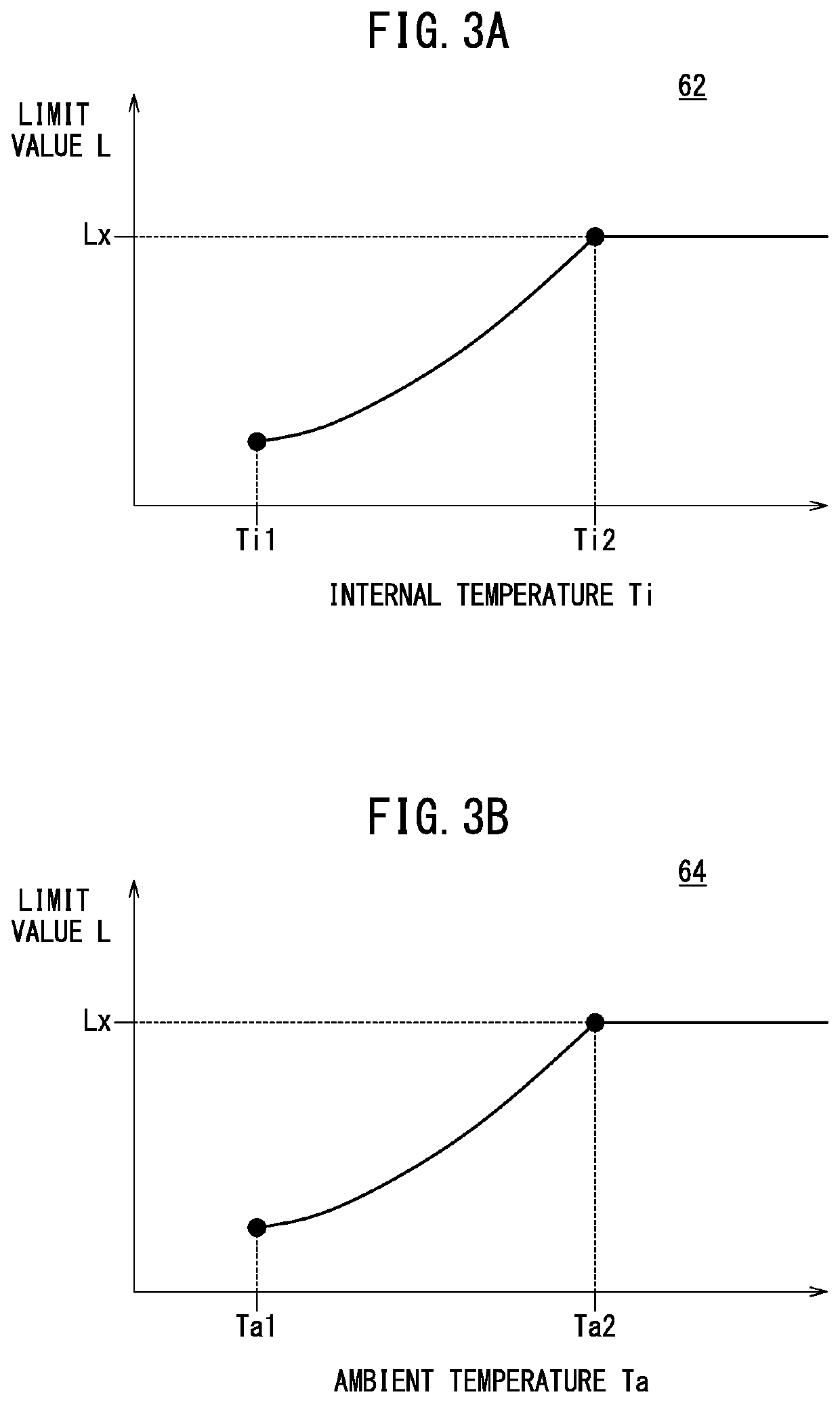
[0036]As shown in FIG. 2, the gas control device 18 includes a high-pressure tank 20, a power plant 30, a sensor group 40, and a g...
first modification
[First Modification]
[0055]In place of the second map 64 as shown in FIG. 3B, the second map 64 shown in FIG. 5 may be used. The second map 64 of FIG. 5 is control information in which a plurality of levels of the control value L, a plurality of ranges of the internal pressure P, and a plurality of ranges of the ambient temperature Ta are associated with each other. This second map 64 associates six pressure ranges (first to sixth pressure ranges), four temperature ranges (first to fourth temperature ranges), and four limit values L (Lx, L1 to L3).
[0056]The pressure ranges are defined by dividing the range from the upper limit to the lower limit of the internal pressure P of the high-pressure tank 20 into six ranges. The pressures in the ranges become larger in the order of first pressure range, second pressure range, third pressure range, fourth pressure range, fifth pressure range, and sixth pressure range. The temperature ranges are defined by dividing the range of the ambient tem...
second modification
[Second Modification]
[0058]In the embodiment described above, if an output abnormality occurs in the internal temperature sensor 42, the discharge control unit 58 obtains the limit value L of the gas flow rate F on the basis of the ambient temperature Ta and the internal pressure P. This embodiment may be modified so that the discharge control unit 58 does not use the information of internal pressure P. That is, the discharge control unit 58 obtains the limit value L of the gas flow rate F on the basis of the ambient temperature Ta, when an output abnormality occurs in the internal temperature sensor 42. Then, the discharge control unit 58 may perform the hydrogen gas discharge control based on the obtained limit value L of the gas flow rate F.
[0059]As shown in FIG. 6, the operations at steps S11 to S15 performed in the second modification are the same as those at steps S1 to S5 of the first embodiment except that the internal pressure P is not used.
[Other Modifications]
[0060]The ab...
PUM
 Abstract
Description
Claims
Application Information
 - R&D
- Intellectual Property
- Life Sciences
- Materials
- Tech Scout
- Unparalleled Data Quality
- Higher Quality Content
- 60% Fewer Hallucinations
Browse by: Latest US Patents, China's latest patents, Technical Efficacy Thesaurus, Application Domain, Technology Topic, Popular Technical Reports.
© 2025 PatSnap. All rights reserved.Legal|Privacy policy|Modern Slavery Act Transparency Statement|Sitemap|About US| Contact US: help@patsnap.com


