Optical sensor with overview camera

Pending Publication Date: 2021-06-24
HEXAGON TECH CENT GMBH
View PDF4 Cites 2 Cited by
  • Summary
  • Abstract
  • Description
  • Claims
  • Application Information

AI Technical Summary

Benefits of technology

The present invention is a device and method for accurately positioning a sensor (measuring probe) in relation to an object for obtaining measuring data. It is designed to provide a robust and reliable positioning even in difficult and challenging measuring conditions. The invention is an optical measuring device that uses triangulation-based methods to determine distance information from a surface or object. Additionally, the invention includes a marking and guiding component that assists operators in positioning and aligning the measuring device with the surface or object in a predefined measuring range.

Problems solved by technology

For inspecting an object to be measured it can be hard to position the sensor at the correct orientation relative to the object.
However, application of this approach may be limited for measuring large and / or complex parts.
For example, if a machine or part to inspect is large and the operator cannot get close to see the zone where the measurement takes place correct positions may still be difficult.
Alternatively, if the part is complex and / or has a lot of parts / fixtures which obscure the view or if the standoff from the sensor to the part is hard to gauge without additional assistance position may become even difficult.
This problem is particularly noticeable for optical sensors where there is no physical probe tip to position near the surface of a part.
Therefore, there remains a problem of providing reliable and robust positioning of the sensor relative to the object.

Method used


Image

  • Optical sensor with overview camera
  • Optical sensor with overview camera
  • Optical sensor with overview camera

Examples


Embodiment Construction

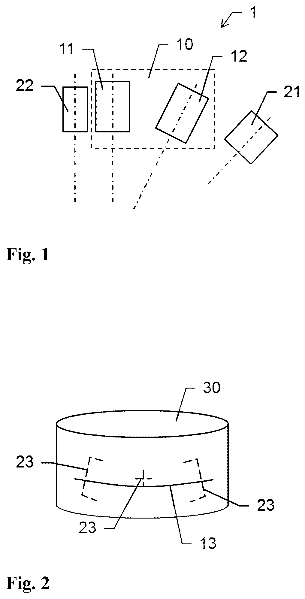
[0069]FIG. 1 shows an embodiment of a measuring system 1 according to the invention. The system comprises a triangulation device 10, an overview camera 22 (OVC) and a projector 21 for providing a visual guide. The triangulation device 10 comprises a light emitting unit 11, e.g. a laser source, and a light receiving unit 12, e.g. a camera, the relative positions and orientations of which are known. As shown, the light emitting unit 11 may be aligned to be parallel to the overview camera 22. However, according to an alternative embodiment of the invention, the light emitting unit 11 may be aligned so that an optical axis of the light emitting unit 11 is tilted relative to an optical axis of the overview camera 22.

[0070]The device works according to the principle of triangulation which is to send out light in one known direction from a known position and receive reflected light from a second known position and measure the angle of the incoming light.

[0071]The light emitting unit 11 com...


PUM


Abstract

A measuring system for triangulation-based distance measuring device having a light emitting unit, a light receiving unit for detecting measuring light reflected from an object and a processing unit for deriving distance information based on a detected reflection of measuring light. The system comprises a visual guiding unit projecting a visual marker onto the object. The light emitting unit and the visual guiding unit provide a light reflection onto the object by emitting the measuring light and the projection of the visual marker onto the object. The measuring system comprises a camera, the field of view of the camera being greater than the field of view of the light receiving unit and the camera captures an image covering the light reflection and the projection of the visual marker and to provide image information according to a captured image.

Description

CROSS-REFERENCE TO RELATED APPLICATIONS[0001]This application claims priority to European Patent Application No. 19217367.2, filed on Dec. 18, 2019. The foregoing patent application are incorporated herein by reference.FIELD OF THE INVENTION[0002]The present invention generally pertains to an optical measuring device comprising an overview camera in order to provide guidance for measuring an object.BACKGROUND[0003]It is common practice to inspect work pieces subsequent to production e.g. on a coordinate positioning apparatus, such as a coordinate measuring machine (CMM), in order to check for correctness of predefined object parameters, like dimensions and shape of the object. Moreover, a detection of a surface of an unknown object is of interest in many industrial applications. Such measurement typically also may be provided using a coordinate measuring machine or any other suitable type of scanning device.[0004]In a conventional 3-D coordinate measurement machine, a probe head is ...

Claims


Application Information

Patent Timeline
IPC IPC(8): G01C3/02G01B11/00G06T7/70H04N5/225G06T7/521
CPCG01C3/02G01B11/005G06T2207/30204H04N5/2256G06T7/521G06T7/70G01B11/2518G01B11/0608G01B21/047H04N23/56
Inventor ILG, PATRICKWROCLAWSKI, PATRYKWUEST, JONAS
Owner HEXAGON TECH CENT GMBH
Why Eureka
Try Eureka