Laser processing apparatus

Pending Publication Date: 2021-07-01
DISCO CORP
View PDF3 Cites 0 Cited by
  • Summary
  • Abstract
  • Description
  • Claims
  • Application Information

AI Technical Summary

Benefits of technology

The laser processing apparatus described in this patent presents a way to automatically determine the boundaries of processing marks on an image. This is done by analyzing the image using a histogram generating section, which generates a first and second histogram of brightness at different positions in the image. The processing section then uses these histograms to determine the boundary of each region where a processing mark is present. This results in a more efficient and efficient process for creating the processing marks on the image.

Problems solved by technology

However, it is necessary to designate the coordinates of the boundaries every time the position of a processing mark changes, and the operation can be performed only by an operator with expertise; further, it takes time for the operation.

Method used


Image

  • Laser processing apparatus
  • Laser processing apparatus
  • Laser processing apparatus

Examples


first embodiment

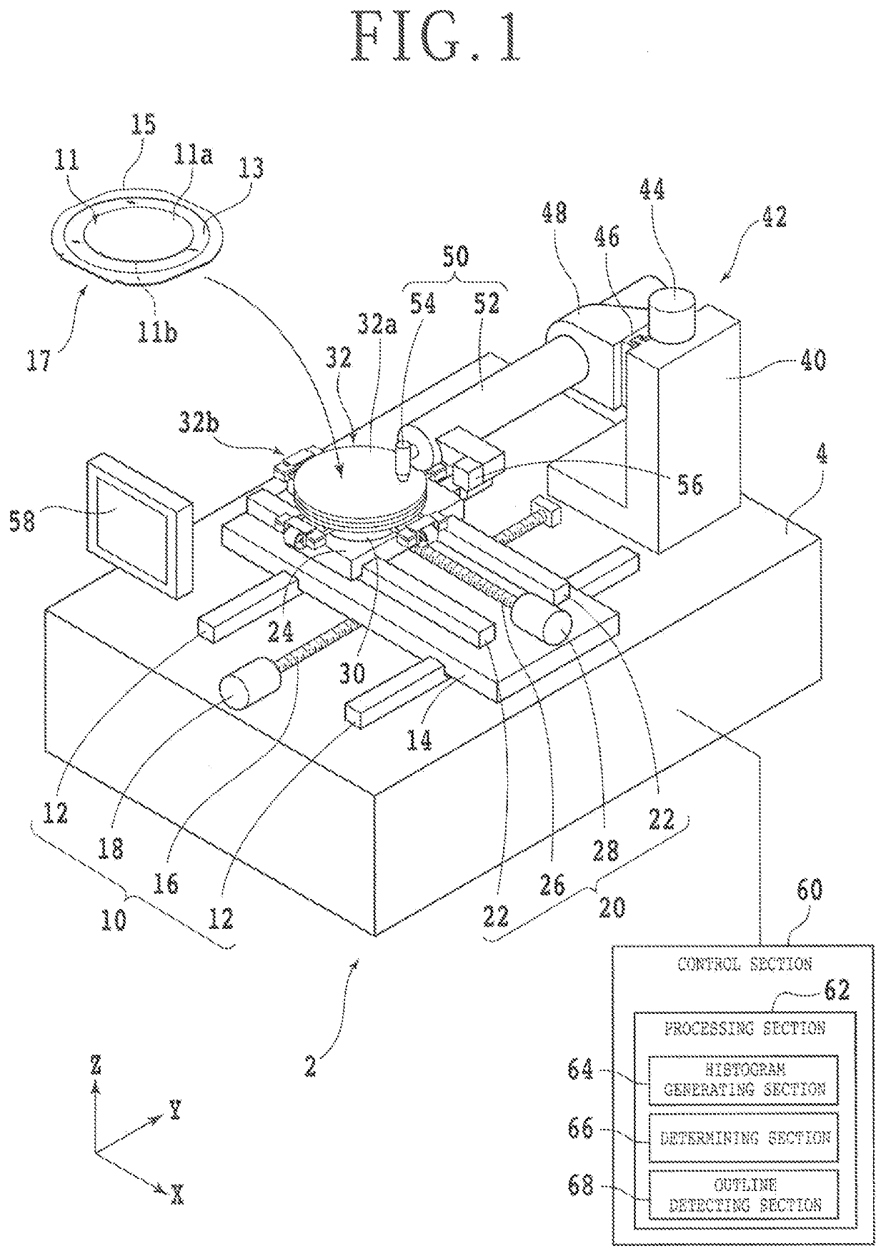
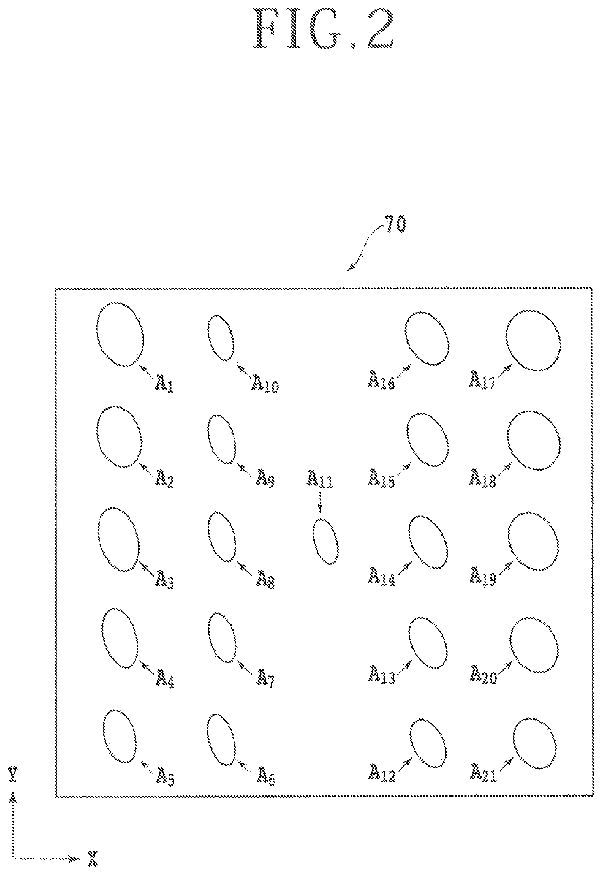
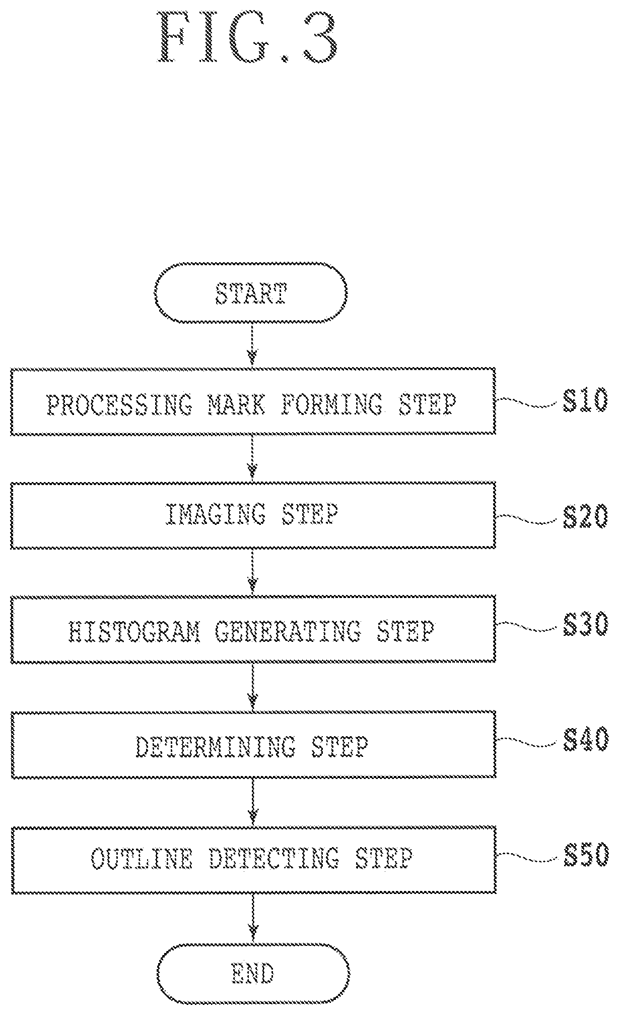
[0039]Next, a method for forming processing marks A (see FIG. 2) on the one surface 11a side of the workpiece 11 by use of the laser processing apparatus 2 and confirming each region where one of the processing marks A is formed, is described. FIG. 3 is a flow chart of the method according to a In this method, first, a processing mark forming step S10 is conducted. In the processing mark forming step S10, the workpiece 11 and the like are held by the chuck table 32 in such a manner that the one surface 11a is exposed to the upper side, after which a pulsed laser beam is applied to the one surface 11a side to process the workpiece 11.

[0040]In the present embodiment, after one processing mark A is formed on the one surface 11a side, the application of the laser beam is once stopped. Then, the chuck table 32 is moved in at least either one direction of the X-axis direction and the Y-axis direction relative to the light concentrator 54 to change the laser beam applying position. After ...

second embodiment

[0056]Incidentally, while an example in which the processing marks A are displayed to be brighter than the background in the image 70 has been described in the above embodiments, the processing marks A may be displayed to be darker than the background in the image 70. In this case, the darkness and brightness are reversed in each histogram, and therefore, contents of processing by the processing section 62 are appropriately adjusted according to the first or Note that the method of confirming the processing marks A as described above is conducted, for example, at the time of processing the workpiece 11 on a trial basis before applying laser lift off processing to the workpiece 11 by use of the laser processing apparatus 2.


PUM

PropertyMeasurementUnit
Brightnessaaaaaaaaaa

Abstract

A laser processing apparatus includes a laser beam applying unit, an imaging unit, and a processing section. The processing unit includes a histogram generating section and a determining section. The histogram generating section generates, from an image obtained by the imaging unit imaging a plurality of processing marks formed by applying the laser beam from the laser beam applying unit to a one-surface side of the workpiece, a first histogram including a plurality of first positions along a first direction of the image and brightness at each of the first positions and a second histogram including a plurality of second positions along a second direction orthogonal to the first direction and brightness at each of the second positions. The determining section determines a boundary of each region where one of the processing marks is formed, based on the first histogram and the second histogram generated by the histogram generating section.

Description

BACKGROUND OF THE INVENTIONField of the Invention[0001]The present invention relates to a laser processing apparatus that applies a laser beam to one-surface side of a workpiece to thereby form a plurality of processing marks, and a method for confirming each region where one of the plurality of processing marks is present.Description of the Related Art[0002]In a laser processing apparatus that applies a laser beam having such a wavelength as to be absorbed by a workpiece to the workpiece to process the workpiece, a shape of the laser beam influences processing quality. The shape of the laser beam is confirmed, for example, by observing results of processing after actually processing the workpiece by the laser beam. In an example, in a case where a one-surface side of a flat plate-shaped workpiece is processed in a linear manner by a laser beam, first, another surface side located opposite to the one surface of the workpiece is held by a holding table provided in the laser processin...

Claims


Application Information

Patent Timeline
IPC IPC(8): B23K26/03B23K26/70
CPCB23K26/032B23K26/707B23K26/00B23K26/0853B23K26/0869B23K2103/56B23K26/0676B23K26/0736B23K26/048B23K26/0006B23K26/40H01L21/3043
Inventor KAWANO, FUMIYA
Owner DISCO CORP
Why Eureka
Try Eureka