

Pantograph Arc Monitoring System and Method
- Summary
- Abstract
- Description
- Claims
- Application Information
AI Technical Summary
Benefits of technology
Problems solved by technology
Method used
Image

Examples
first embodiment
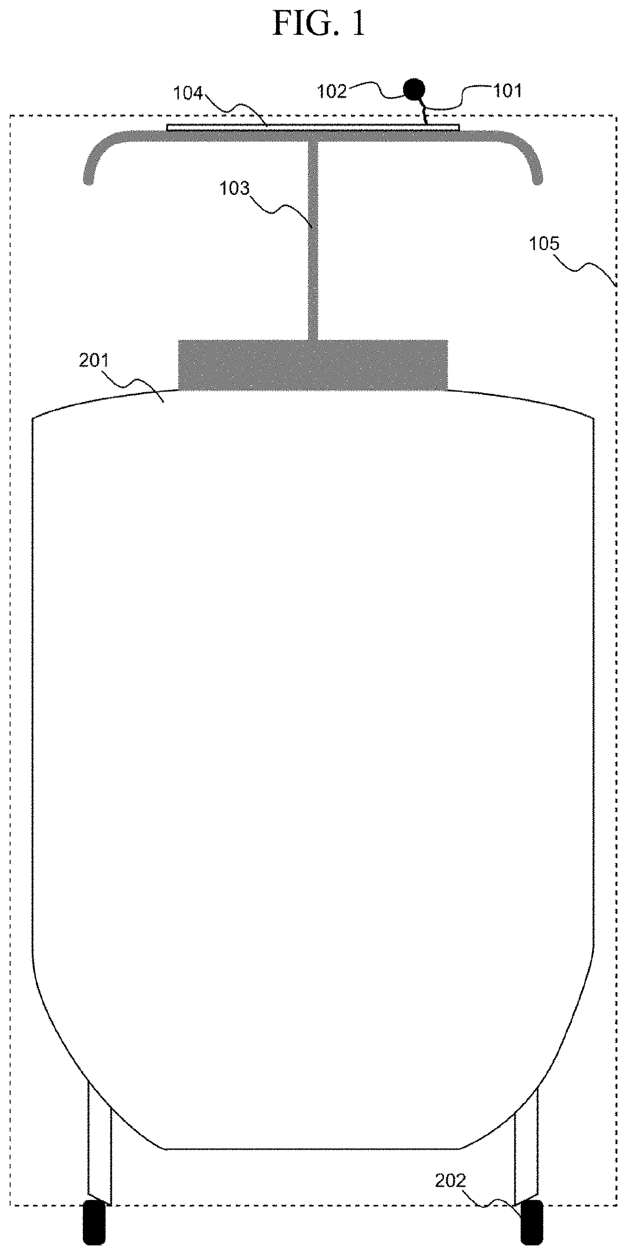
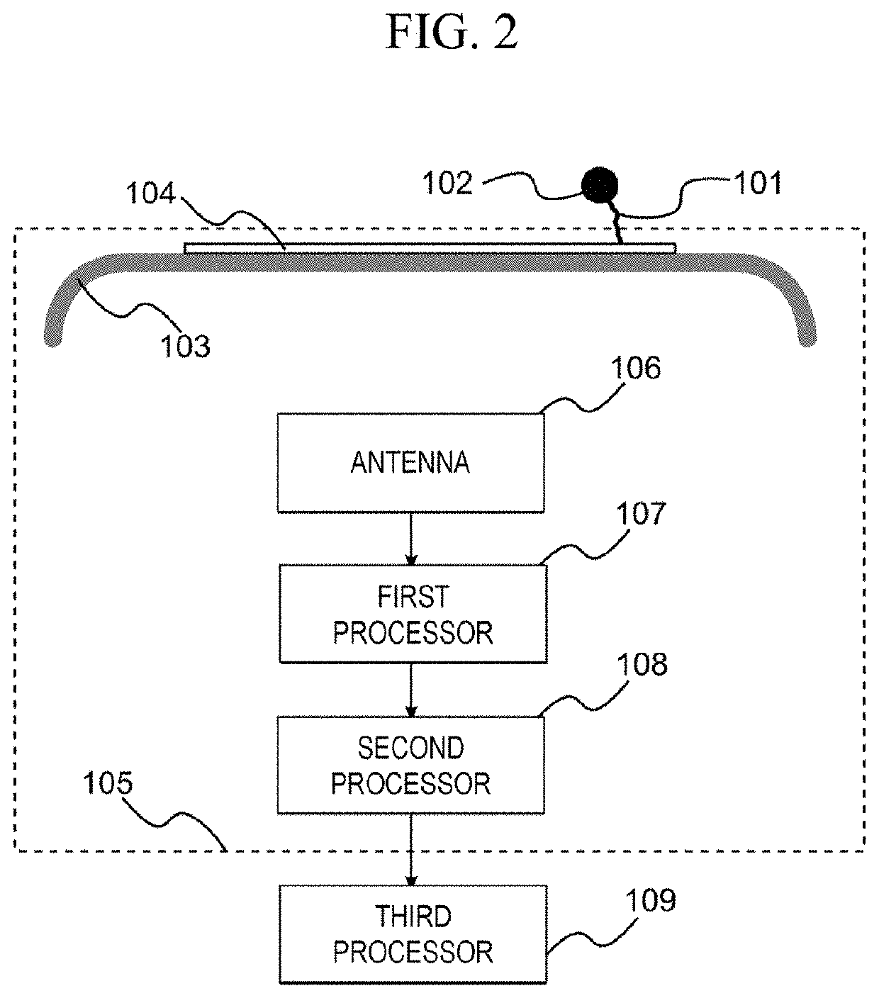
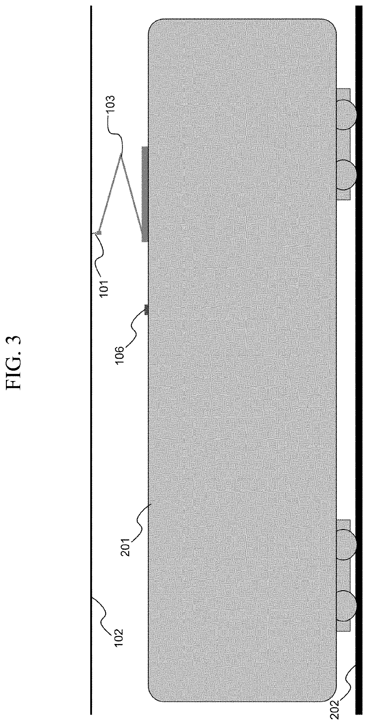
[0063]The system according to the first embodiment estimates the angular position of the arc on the pantograph 103 by using the magnetic field detected by the antennas 401. The estimation is performed substantially in real time by the first processor 107, and the first processor 107 is disposed on the electric vehicle 105 and near the antennas 401. Therefore, the electric vehicle 105 does not need to implement a high-performance processor or a high-speed network channel so as to estimate the arc position. This is because the first processor 107 does not use large-capacity data like a high-resolution camera, and thus it is not necessary to process and transmit such large-capacity data.
[0064]The system according to the first embodiment estimates the state of the pantograph 103 based on the plurality of arc events on the same electric vehicle 105. The estimation can be performed by the second processor 108 on the electric vehicle 105. This is because the data that describes each arc ev...
second embodiment
[0066]In a second embodiment of the disclosure, a specific configuration example of a system will be described. A configuration other than specific details is the same as that of the first embodiment, and thus will not be described again.
[0067]FIG. 12 is a configuration of a first processor according to the second embodiment. In the configuration in FIG. 12, the first processor 107 receives power from an energy harvesting unit 1201 and communicates with the second processor 108 via a wireless connection. In this way, the cable connections 502 and 503 that pass through the vehicle body roof 501 are not required. As the energy harvesting unit 1201, any type of unit that acquires electrical energy from environment can be used. The energy harvesting unit 1201 may be disposed near the first processor 107, or may be disposed remotely from the first processor 107 and connected to the first processor 107 by, for example, a power cable.
[0068]In the first embodiment, it is assumed that the se...
PUM
 Abstract
Description
Claims
Application Information