
Position detection apparatus, method, and system utilizing an array of magnetic sensors each comprising a sensor signal conditioning circuit

Pending Publication Date: 2021-07-15
HONEYWELL INT INC
View PDF3 Cites 1 Cited by
  • Summary
  • Abstract
  • Description
  • Claims
  • Application Information

AI Technical Summary

Benefits of technology

The position detection apparatus described in the patent allows for faster and more accurate position detection of a magnet compared to conventional systems. It uses a dedicated sensor signal conditioning circuit for each magnet sensor in an array, resulting in reduced warm up time, faster response time, lower power consumption, and improved output resolution of the magnet sensor array. Additionally, the apparatus allows for updating and polling of the magnet sensors in parallel, providing more efficient and accurate position detection.

Problems solved by technology

In some embodiments, the digital position data comprises errors associated with at least one of an offset error, a sensitivity / gain error, a thermal effect on offset error, or a thermal effect on sensitivity / gain error.

Method used


Image

  • Position detection apparatus, method, and system utilizing an array of magnetic sensors each comprising a sensor signal conditioning circuit
  • Position detection apparatus, method, and system utilizing an array of magnetic sensors each comprising a sensor signal conditioning circuit
  • Position detection apparatus, method, and system utilizing an array of magnetic sensors each comprising a sensor signal conditioning circuit

Examples


Embodiment Construction

[0020]Some embodiments of the present invention will now be described more fully hereinafter with reference to the accompanying drawings, in which some, but not all, embodiments of the invention are shown. Indeed, various embodiments of the invention may be embodied in many different forms and should not be construed as limited to the embodiments set forth herein; rather, these embodiments are provided so that this disclosure will satisfy applicable legal requirements. Like reference numerals refer to like elements throughout. As used herein, the terms “data,”“content,”“information,” and similar terms may be used interchangeably to refer to data capable of being transmitted, received and / or stored in accordance with embodiments of the present invention. Thus, use of any such terms should not be taken to limit the spirit and scope of embodiments of the present invention.

[0021]Additionally, as used herein, the term “circuitry” refers to (a) hardware-only circuit implementations (e.g.,...


PUM


Abstract

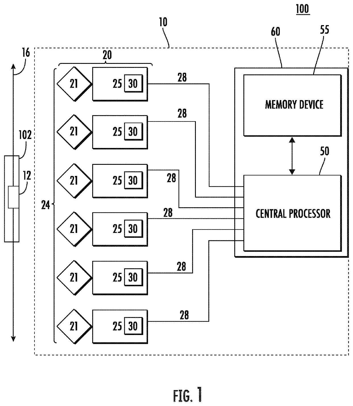
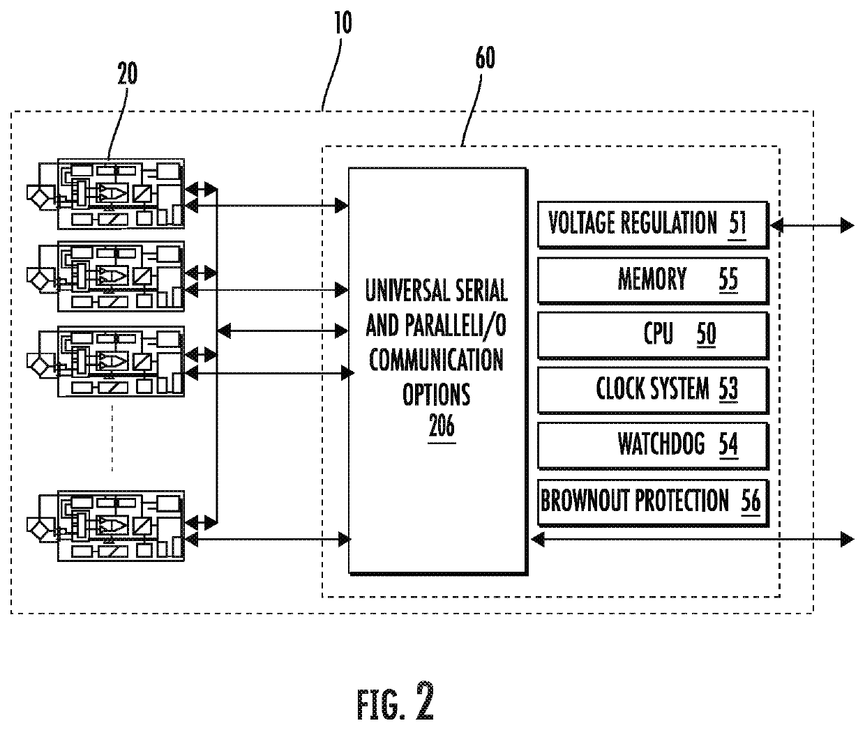
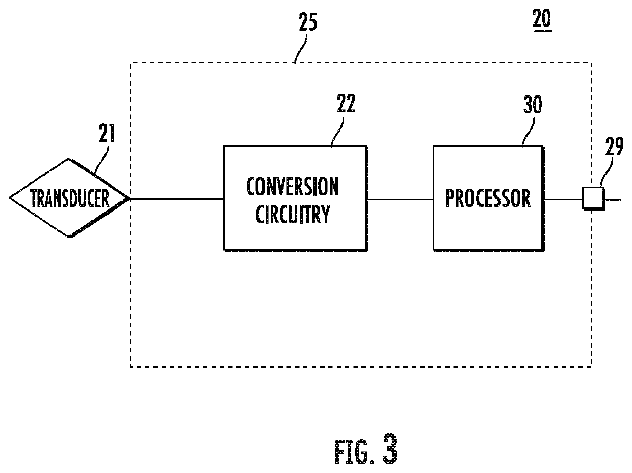
An apparatus, method, and associated systems are provided. A plurality of anisotropic magnetoresistive sensors are arranged in an array, each anisotropic magnetoresistive sensor comprising a magnetic field transducer and a sensor signal conditioning circuit. A central processor in electrical communication with each anisotropic magnetoresistive sensor is provided. The central processor is configured to compare processed signals received from at least two of the plurality of anisotropic magnetoresistive sensors to determine a position of the magnet.

Description

TECHNOLOGICAL FIELD[0001]An example embodiment relates generally to a position detection apparatus, and, more particularly, to apparatus and techniques for determining a position of a magnet.BACKGROUND[0002]Magnetoresistive (MR) array technology is utilized in a variety of commercial, consumer and industrial detection applications. In some MR systems, an apparatus may be provided for determining the position of a member movable along a path. In such a device, a magnet may be attached to the movable member and an array of magnetic field transducers are located adjacent the path. As the magnet approaches, passes and moves away from a transducer, the transducer provides a varying output signal, which may be represented by a single characteristic curve that is representative of any of the transducers.[0003]One example of a conventional magnetic sensing approach is disclosed, for example, in U.S. Pat. No. 5,589,769, “Position Detection Apparatus Including a Circuit for Receiving a Plural...

Claims


Application Information

Patent Timeline
IPC IPC(8): G01D5/16
CPCG01D5/16G01D5/145G01D3/02G01D5/244G01D5/245G01R33/0017G01R33/0094G01R33/09
Inventor RICKS, LAMAR FLOYD
Owner HONEYWELL INT INC
Learn More