Class of Over-Constrained Two-Rotation Parallel Mechanism with Same Kinematics

Active Publication Date: 2021-07-22
YANSHAN UNIV
View PDF0 Cites 0 Cited by
  • Summary
  • Abstract
  • Description
  • Claims
  • Application Information

AI Technical Summary

Benefits of technology

The present invention proposes a new type of parallel mechanism that overcomes the shortcomings of previous designs. It has high rigidity, a large working space, perpendicular rotation axes, easy-to-control calibration, and the same kinematics but different structures. The mechanism consists of four constrained branches, and each one is an over-constrained mechanism with two perpendicular rotating axes. This new mechanism has simple kinematics, is easy to control, and can handle large loads. Overall, the invention offers a solution for various applications requiring high precision and rigidity.

Problems solved by technology

However, no related patents for over-constrained two-rotation parallel mechanisms with same kinematics have been found.

Method used


Image

  • Class of Over-Constrained Two-Rotation Parallel Mechanism with Same Kinematics
  • Class of Over-Constrained Two-Rotation Parallel Mechanism with Same Kinematics

Examples


embodiment 1

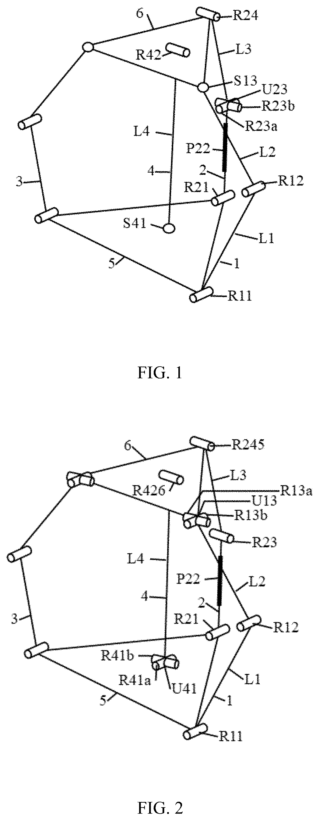
[0018]The present invention provides a class of over-constrained two-rotation parallel mechanism with same kinematics, as shown in FIG. 1, which includes a base 5, a moving platform 6 and four branches connecting the base and the moving platform, the base 5 and the moving platform 6 are both equilateral triangles, and the four branches connecting the base 5 and the moving platform 6 include a first branch 1, a second branch 2, a third branch 3, and a fourth branch 4. Both ends of each of the first branch 1, the second branch 2, and the third the branch 3 are respectively connected to the end points of the base 5 and the moving platform 6, both ends of the fourth branch 4 are respectively connected to the center points of the base 5 and the moving platform 6, the first branch 1 and the second branch 2 are driving branches, and the first rotating pair R11 in the first branch 1 and the first moving pair P22 in the second branch 2 are both driving pairs.

[0019]The first branch 2 and the ...

embodiment 2

[0022]The technical solution adopted in the second aspect of the present invention, as shown in FIG. 2, includes a base 5, a moving platform 6, and four branches connecting the base and the moving platform. The base 5 and the moving platform 6 are both equilateral triangles, and the four branches connecting the base 5 and the moving platform 6 include a first branch 1, a second branch 2, a third branch 3, and a fourth branch 4. Both ends of each of the first branch 1, the second branch 2, and the third branch 3 are respectively connected to the end points of the base 5 and the moving platform 6, both ends of the fourth branch 4 are respectively connected to the center points of the base 5 and the moving platform 6. The first branch 1 and the second branch 2 are driving branches, and the first rotating pair R11 in the first branch 1 and the first moving pair P22 in the second branch 2 are both driving pairs.

[0023]The first branch 1 and the third branch 3 alternatively consist of a fi...

embodiment 3

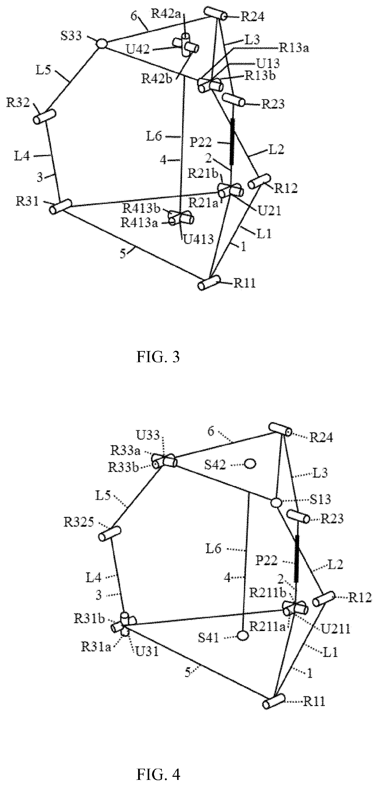
[0026]The technical solution adopted in the third aspect of the present invention, as shown in FIG. 3, includes a base 5, a moving platform 6, and four branches connecting the base and the moving platform. The base 5 and the moving platform 6 are both equilateral triangles, and the four branches connecting the base 5 and the moving platform 6 include a first branch 1, a second branch 2, a third branch 3, and a fourth branch 4. Both ends of each of the first branch 1, the second branch 2, and the third branch 3 are respectively connected to the end points of the base 5 and the moving platform 6, both ends of the fourth branch 4 are respectively connected to the center points of the base 5 and the moving platform 6. The first branch 1 and the second branch 2 are driving branches, and the first rotating pair R11 in the first branch 1 and the first moving pair P22 in the second branch 2 are both driving pairs.

[0027]The first branch 1 alternatively consists of a first rotating pair R11, ...


PUM


Abstract

The present invention relates to a class of over-constrained two-rotation parallel mechanism with same kinematics, which comprises a base, a moving platform and four branches connecting the base and the moving platform, wherein the base and the moving platform are equilateral triangles, both ends of each of the first branch, the second branch and the third branch are respectively connected to end points of the base and the moving platform, both ends of the fourth branch are respectively connected to center points of the base and the moving platform, the first branch and the third branch both consist of a first rotating pair. The parallel mechanism of the present invention has a large rotation space and high rigidity, and can be used for positioning equipment such as missile launchers.

Description

TECHNICAL FIELD[0001]The invention belongs to the field of parallel mechanisms, and particularly relates to a class of over-constrained two-rotation parallel mechanism with same kinematics.BACKGROUND TECHNOLOGY[0002]The two-rotation parallel mechanism has a wide range of promising applications for satellite tracking, medical equipment, motion simulation, platform attitude adjustment, etc. The two-rotation parallel mechanism includes two forms: over-constrained and non-over-constrained. At present, the research on the non-over-constrained two-rotation parallel mechanism is more in-depth, such as Chinese patent CN200610102017.3, CN201610303875.8, CN201610989566.0, CN2016109895660 proposed mechanism with simple structure and flexible rotation, but less rigidity compared with the over-constrained two-rotation parallel mechanism; in the two-rotation over-constrained parallel mechanism proposed by Chinese patent CN201310600845.X, the motion is completely decoupled and easy to control.[000...

Claims


Application Information

Patent Timeline
IPC IPC(8): F16H21/46
CPCF16H21/46B25J9/0045B25J9/0072
Inventor YE, NIJIAHU, BOZHAO, JINJUNZHANG, DAXU, LUZHOUWANG, KAIXIE, TENGFEI
Owner YANSHAN UNIV
Why Eureka
Try Eureka