
Leadframe, Encapsulated Package with Punched Lead and Sawn Side Flanks, and Corresponding Manufacturing Method

a manufacturing method and leadframe technology, applied in the direction of electrical equipment, semiconductor devices, semiconductor/solid-state device details, etc., can solve the problems of difficult forming of encapsulant bars along the longer side of the leadframe, less challenging, and difficulty in handling individual carriers, so as to reduce processing complexity and high device reliability

Pending Publication Date: 2021-07-22
INFINEON TECH AG
View PDF1 Cites 3 Cited by
  • Summary
  • Abstract
  • Description
  • Claims
  • Application Information

AI Technical Summary

Benefits of technology

The patent aims to create packages that have a focus on reducing processing complexity while maintaining high device reliability.

Problems solved by technology

It has turned out that forming encapsulant bars along the longer side of the leadframe may be difficult, while sawing along this direction may be less challenging.
In particular before encapsulation, said individual carriers may be difficult to handle in the absence of connecting structures such as tie bars.

Method used


Image

  • Leadframe, Encapsulated Package with Punched Lead and Sawn Side Flanks, and Corresponding Manufacturing Method
  • Leadframe, Encapsulated Package with Punched Lead and Sawn Side Flanks, and Corresponding Manufacturing Method
  • Leadframe, Encapsulated Package with Punched Lead and Sawn Side Flanks, and Corresponding Manufacturing Method

Examples


Embodiment Construction

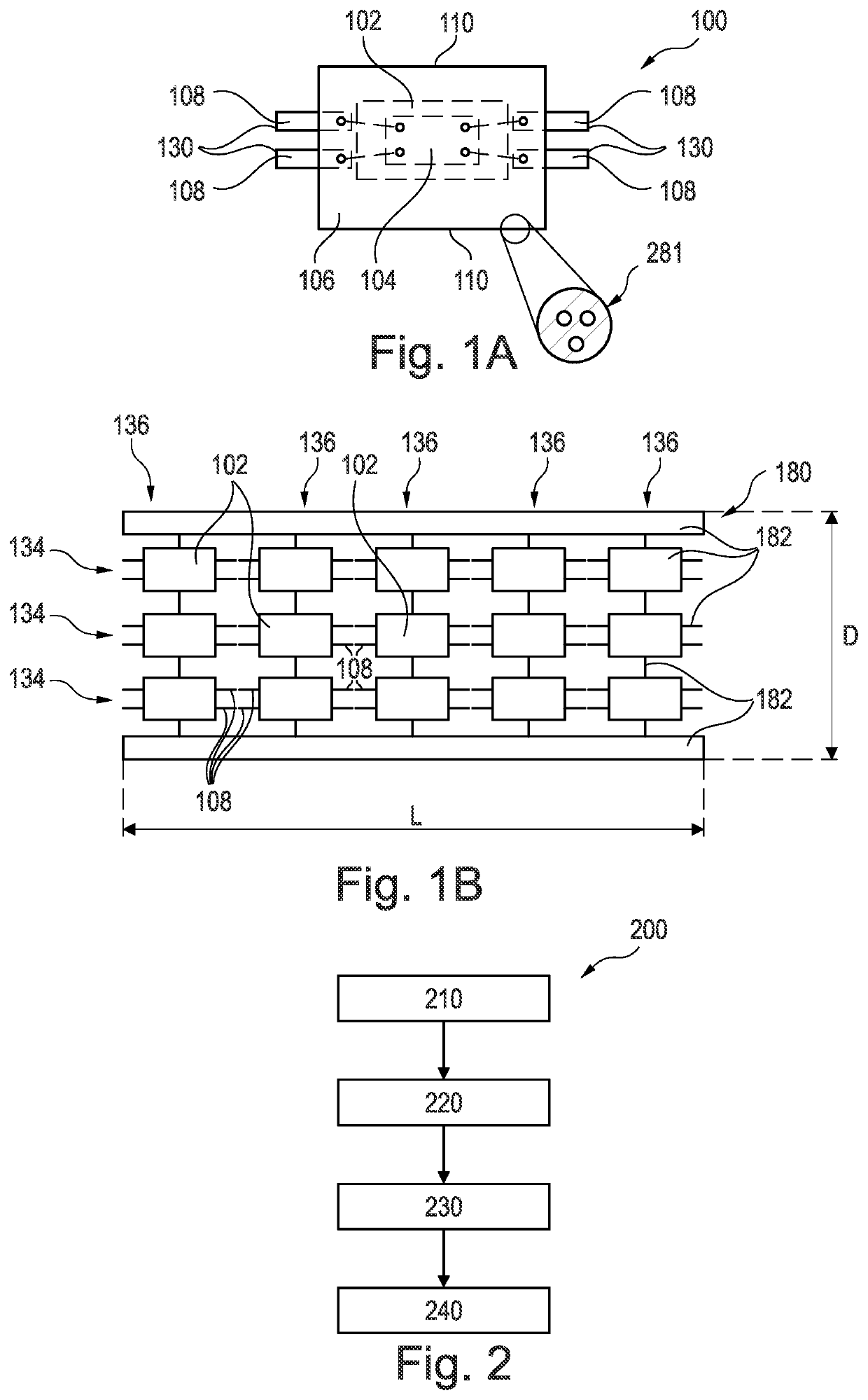
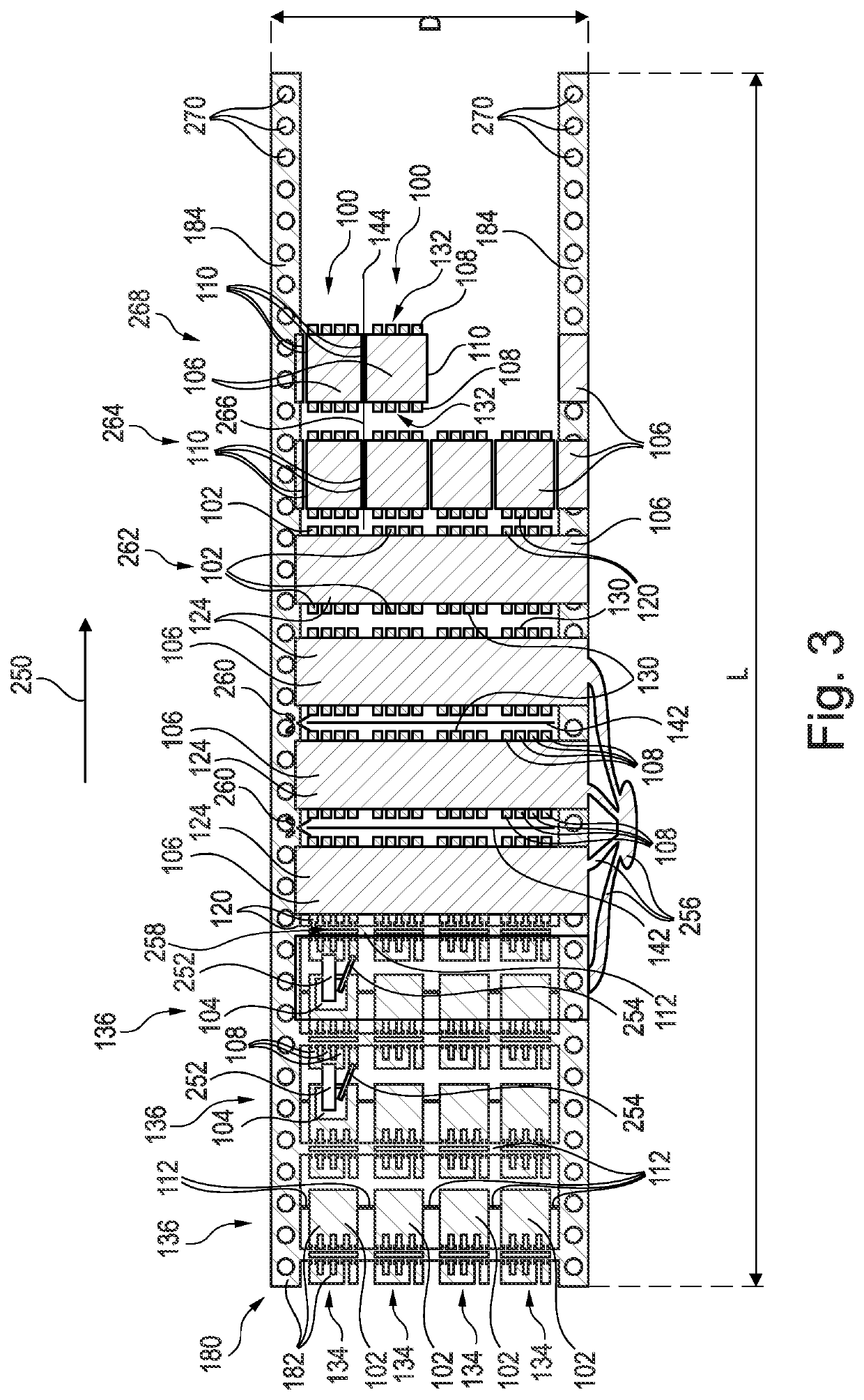
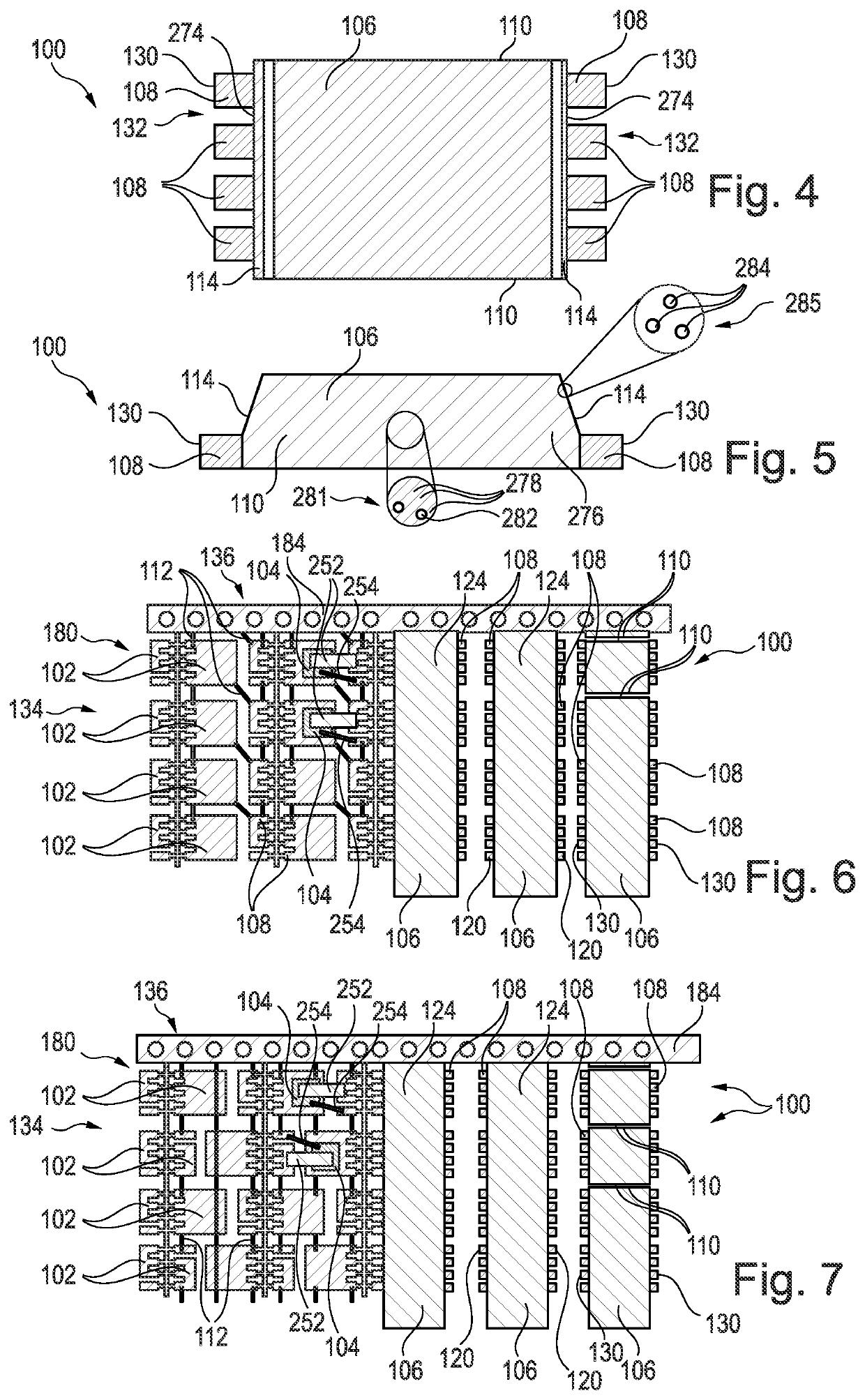
[0095]In the following, further exemplary embodiments of the package, the leadframe concept and the method will be explained.

[0096]In the context of the present application, the term “package” may particularly denote an electronic device which may comprise one or more electronic components mounted on a carrier, said carrier to comprise or consist out of a single part, multiple parts joined via encapsulation or other package components, or a subassembly of carriers. Said constituents of the package may be encapsulated at least partially by an encapsulant. Optionally, one or more electrically conductive interconnect bodies (such as bond wires and / or clips) may be implemented in a package, for instance for electrically coupling the electronic component with the carrier.

[0097]In the context of the present application, the term “electronic component” may in particular encompass a semiconductor chip (in particular a power semiconductor chip), an active electronic device (such as a transis...


PUM


Abstract

A package includes a carrier, an electronic component on the carrier, an encapsulant encapsulating at least part of the carrier and the electronic component, and at least one lead extending beyond the encapsulant and having a punched surface, wherein at least part of at least one side flank of the encapsulant has a sawn texture.

Description

TECHNICAL FIELD[0001]Various embodiments relate generally to a package, a leadframe, and a method of manufacturing a package.DESCRIPTION OF THE RELATED ART[0002]Packages may be denoted as encapsulated electronic components with electrical connections extending out of the encapsulant and being mounted to an electronic periphery, for instance on a printed circuit board.[0003]Packaging cost is an important driver for the industry. Related with this are performance, dimensions and reliability. The different packaging solutions are manifold and have to address the needs of the application.SUMMARY[0004]There may be a need to provide a possibility to manufacture packages with the focus to reduce processing complexity while maintaining high device reliability.[0005]According to an exemplary embodiment, a package is provided which comprises a carrier, an electronic component on the carrier, an encapsulant encapsulating at least part of the carrier and the electronic component, and at least o...

Claims


Application Information

Patent Timeline
Patent Type & Authority Applications(United States)
IPC IPC(8): H01L23/495H01L23/31H01L21/48H01L21/56
CPCH01L23/49565H01L23/3107H01L23/4952H01L21/565H01L23/49575H01L21/4825H01L21/4842H01L23/49524H01L21/56H01L23/49541H01L23/49562H01L23/49548H01L21/561H01L2224/49111H01L2224/48247H01L2224/97H01L2924/181H01L2924/00012
Inventor SINGER, FRANKBOEHM, MARCUSGRASSMANN, ANDREASGRUBER, MARTINSCHINDLER, UWE
Owner INFINEON TECH AG
Learn More