Inclination adjusting mechanism

a technology of adjusting mechanism and inclination, which is applied in the direction of grinding drive, manufacturing tools, lapping machines, etc., can solve the problems of reducing the inclination adjusting mechanism, changing the inclination of the holding surface relative to the lower surface of the grindstone, and shrinking the inclination of the holding surface, etc., to achieve uniform thickness of workpieces, increase the area of supporting the chuck table, and enhance rigidity.

Pending Publication Date: 2021-07-29
DISCO CORP
View PDF15 Cites 2 Cited by
  • Summary
  • Abstract
  • Description
  • Claims
  • Application Information

AI Technical Summary

Benefits of technology

[0008]In the inclination adjusting mechanism according to one aspect of the present invention, the upper ring plate, the lower ring plate, and the base are connected by the connecting mechanism after the inclination of the holding surface is adjusted by rotating one of or both the upper ring plate and the lower ring plate. Therefore, an area for supporting the chuck table is enlarged and rigidity is also enhanced, as compared to an existing inclination adjusting mechanism in which the chuck table is supported by three vertically movable columns or three vertically movable blocks disposed under the chuck table. For this reason, for example, even when a step of grinding a workpiece by a grindstone while exerting a high load is conducted, a situation in which the parallelism of the holding surface relative to the lower surface of the grindstone would be changed during grinding is prevented, and it is possible to make uniform accuracy of a thickness of the workpiece after grinding.
[0009]In the case where the first bearing and the second bearing each include an air bearing and a flow channel for forming the first bearing and the second bearing which are air bearings is caused by a connecting mechanism to communicate with a suction source, the first bearing and the second bearing which are air bearings can easily be made to disappear after the inclination of the holding surface is adjusted by rotating one of or both the upper ring plate and the lower ring plate, and, further, the upper ring plate, the lower ring plate, and the base can easily be connected by a suction force generated by the suction source.

Problems solved by technology

Therefore, when the workpiece held on the chuck table is ground by a grindstone while pressing from above, a high load is exerted on the inclination adjusting mechanism, whereby the inclination adjusting mechanism shrinks, and there arises a problem that the inclination, in other words, parallelism, of the holding surface relative to the lower surface of the grindstone would be changed.

Method used


Image

  • Inclination adjusting mechanism
  • Inclination adjusting mechanism
  • Inclination adjusting mechanism

Examples


first embodiment

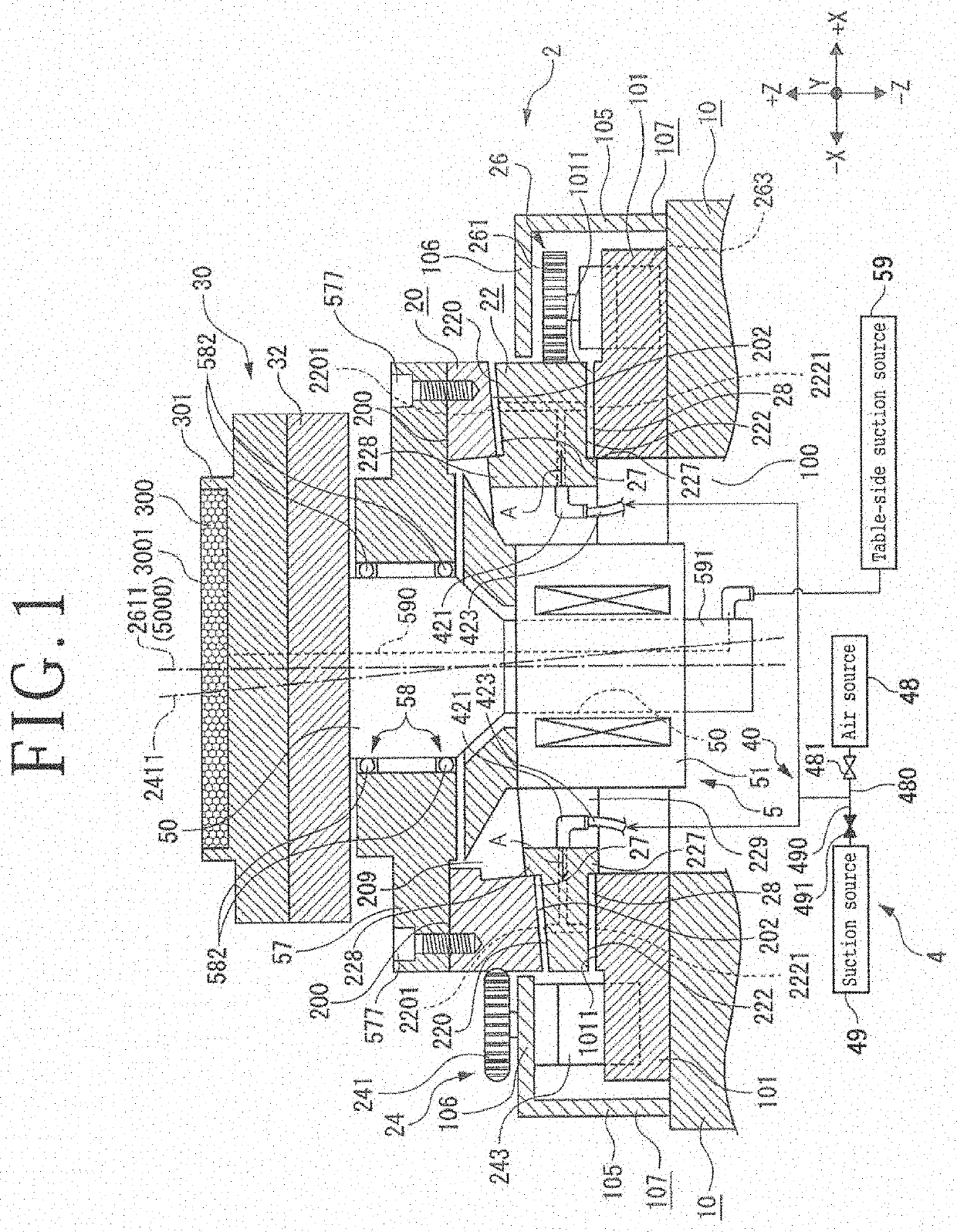
[0046]In the present embodiment, the first bearing 27 between the lower surface 202 of the upper ring plate 20 and the upper surface 220 of the lower ring plate 22 and the second bearing 28 between the lower surface 222 of the lower ring plate 22 and the upper surface 1011 of the base 10, depicted in FIG. 1, include air bearings. The connecting mechanism 4 is configured to cause a flow channel 40 for forming the first bearing 27 and the second bearing 28 which are air bearings to communicate with the suction source 49 depicted in FIG. 1. Hereinafter, the connecting mechanism 4 will be a connecting mechanism 4 in the

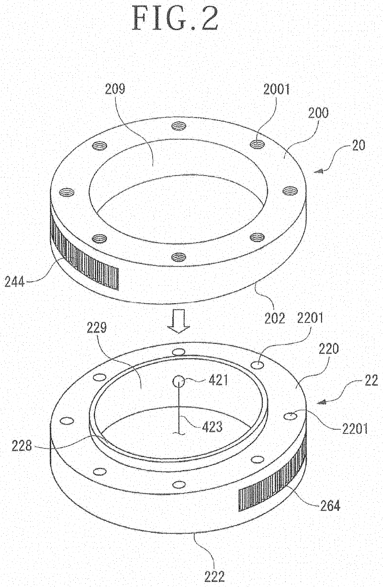
[0047]For example, as depicted inFIG. 1, the upper surface 220 of the lower ring plate 22 is formed with an upper surface air jetting passage 2201 for jetting air A toward the upper side, at even intervals in the circumferential direction. In addition, the lower surface 222 of the lower ring plate 22 is formed with lower surface air jetting passages 2221 for jetting air A...

second embodiment

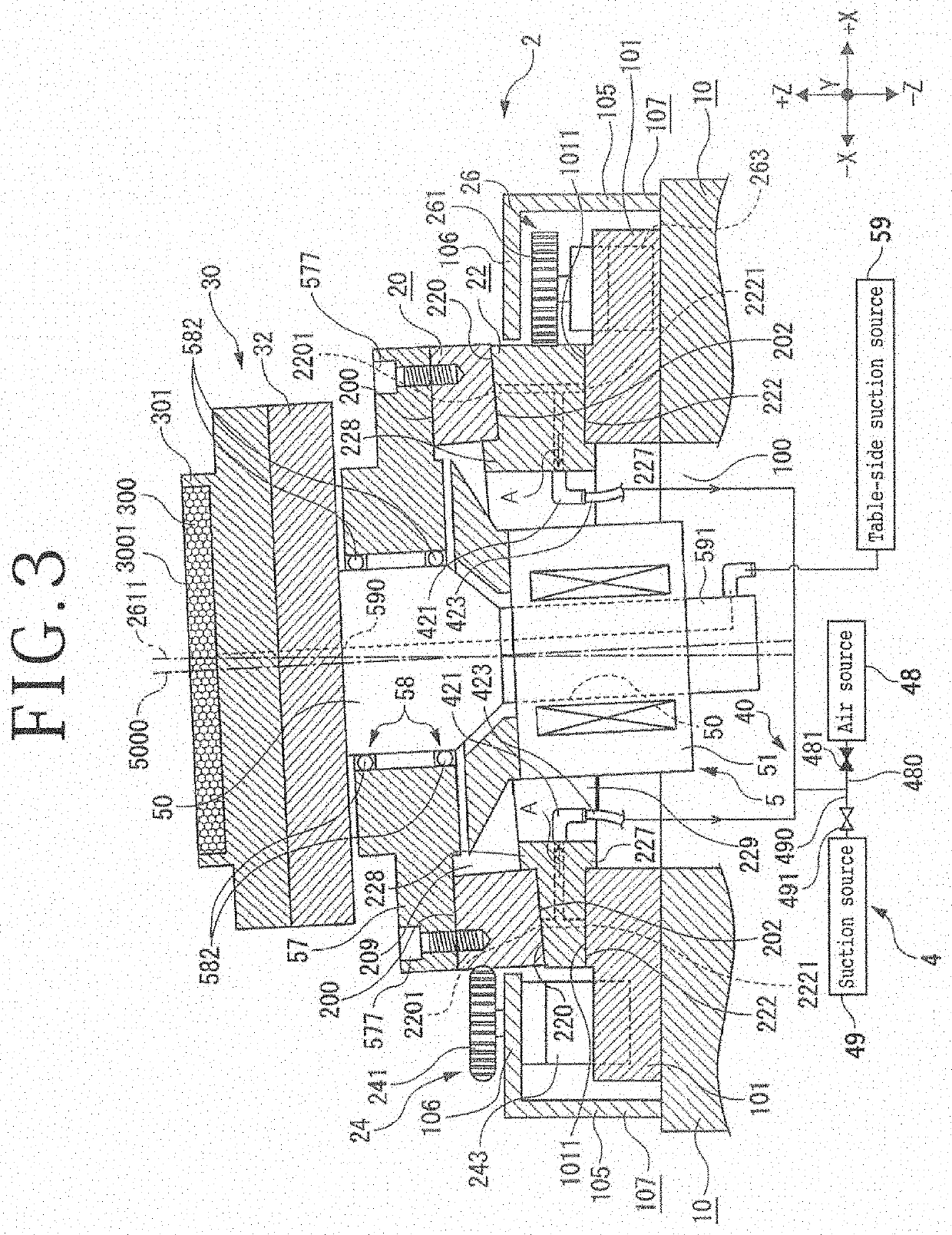
[0077]The connecting mechanism 4 of the inclination adjusting mechanism 2 is not limited to, for example, the configuration depicted in FIG. 3. The inclination adjusting mechanism 2 may include, for example, a connecting mechanism (connecting means) 41 illustrated in FIG. 5. Hereinafter, the connecting mechanism 41 will be the connecting mechanism 41 in the

[0078]While the connecting mechanism 4 in the first embodiment depicted in FIG. 3 has a configuration in which the flow channel 40 communicates with the suction source 49 and the upper ring plate 20, the lower ring plate 22, and the base 10 are connected by the suction source generated by the suction source 49, the connecting mechanism 41 in the second embodiment includes an electromagnet 45 capable of magnetically attaching the upper ring plate 20, the lower ring plate 22, and the base 10 to one another.

[0079]For example, the lower ring plate 22 includes a material which is highly rigid and is attracted by a magnetic force (for e...


PUM


Abstract

There is provided an inclination adjusting mechanism including an annular upper plate that has an upper surface for connecting a table and a lower surface inclined relative to the upper surface, an annular lower plate that has an upper surface parallel to the lower surface of the upper plate and a lower surface parallel to the upper surface of the upper plate and facing an upper surface of a base, an upper rotating mechanism that rotates the upper plate, a lower rotating mechanism that rotates the lower plate, a first bearing provided between the lower surface of the upper plate and the upper surface of the lower plate, a second bearing provided between the lower surface of the lower plate and the upper surface of the base, and a connecting mechanism that connects the upper plate, the lower plate, and the base.

Description

BACKGROUND OF THE INVENTIONField of the Invention[0001]The present invention relates to an inclination adjusting mechanism for adjusting an inclination of a holding surface of a chuck table.Description of the Related Art[0002]A grinding apparatus that grinds a workpiece such as a semiconductor wafer held by a holding surface of a chuck table by a grindstone includes an inclination adjusting mechanism capable of adjusting parallelism of the holding surface relative to a lower surface of the grindstone, as disclosed, for example, in Japanese Patent Laid-Open No. 2004-082291 or Japanese Patent Laid-Open No. 2008-238341.SUMMARY OF THE INVENTION[0003]In the above-mentioned inclination adjusting mechanism, a lower surface of the chuck table is supported at three points arranged at even intervals in the circumferential direction. Therefore, when the workpiece held on the chuck table is ground by a grindstone while pressing from above, a high load is exerted on the inclination adjusting mec...

Claims


Application Information

Patent Timeline
Patent Type & Authority Applications(United States)
IPC IPC(8): B23Q3/04
CPCB23Q3/04B24B41/068B24B37/30B24B41/02B24B47/12B24B47/00B24B37/34B23Q2220/004B23Q3/088B23Q1/0027H01L21/68764H01L21/68785H01L21/6838B24B37/04H01L21/67092B23Q3/186
Inventor YAMAHATA, ICHIRO
Owner DISCO CORP
Why Eureka
Try Eureka