Illuminated suction device

a suction device and illumination technology, applied in the field of surgical instruments with compact illumination assemblies, can solve the problems of difficult and often impossible to prevent the suction device from interfering with the desired visualization and illumination, limited flexibility of the light guide, and hampering the use of the tool by the surgeon, so as to eliminate the formation of shadows

Active Publication Date: 2021-08-05
OBP SURGICAL CORP
View PDF4 Cites 0 Cited by
  • Summary
  • Abstract
  • Description
  • Claims
  • Application Information

AI Technical Summary

Benefits of technology

[0010]The present invention provides an improved illuminated medical device, such as a Yankauer suction device, which provides a uniform illuminance pattern over a circular target area and eliminates formation of a shadow from the medical device in the illuminated target area. The target area (target surface) is a surface in contact with or near the distal tip of the suction tube and substantially perpendicular to the distal tip of the suction tube.
[0011]Moreover, the illuminated medical device of the present invention provides bright illumination, without increasing the bulk of the device so that the device can be inserted into small spaces and so that the illumination assembly does not obscure the surgeon's field of view. Specifically, the illuminated medical device of the present invention achieves an improved level of illuminance for a sufficient time duration, while keeping the size and weight of the onboard energy source (typically batteries) reasonably small for a hand-held tool. In addition, the device of the present invention includes heat dissipation features that prevent the illumination assembly from heating the device and avoid potential injury to patient tissues. Other features of the illuminated medical device of the present invention are described in the detailed description.

Problems solved by technology

Particularly when such a suction device is in place, it is extremely difficult and often impossible to prevent the suction device from interfering with the desired visualization and illumination.
The limited flexibility of the light guide tends to hamper the use of the tool by the surgeon.

Method used


Image

  • Illuminated suction device
  • Illuminated suction device
  • Illuminated suction device

Examples


Embodiment Construction

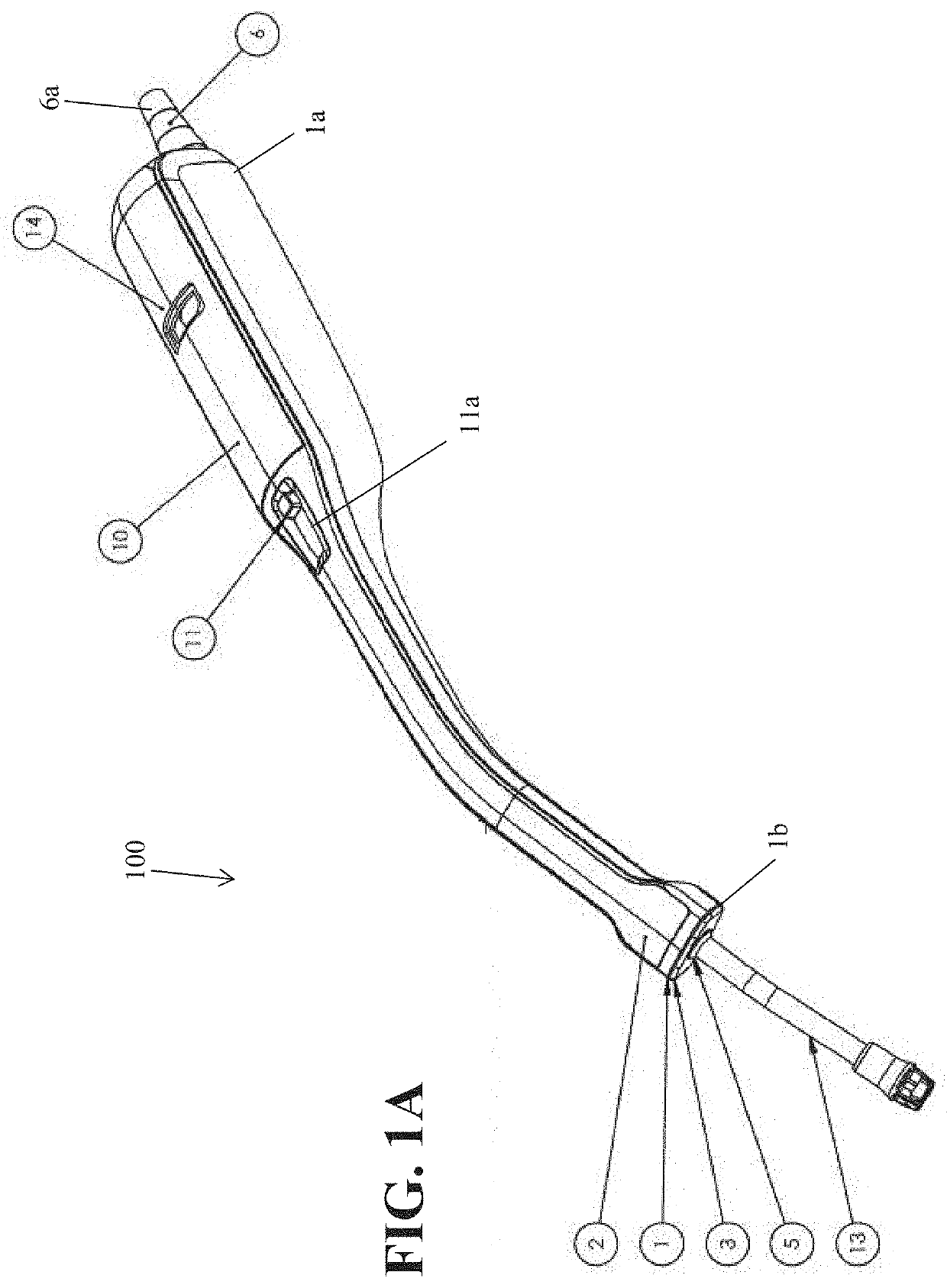
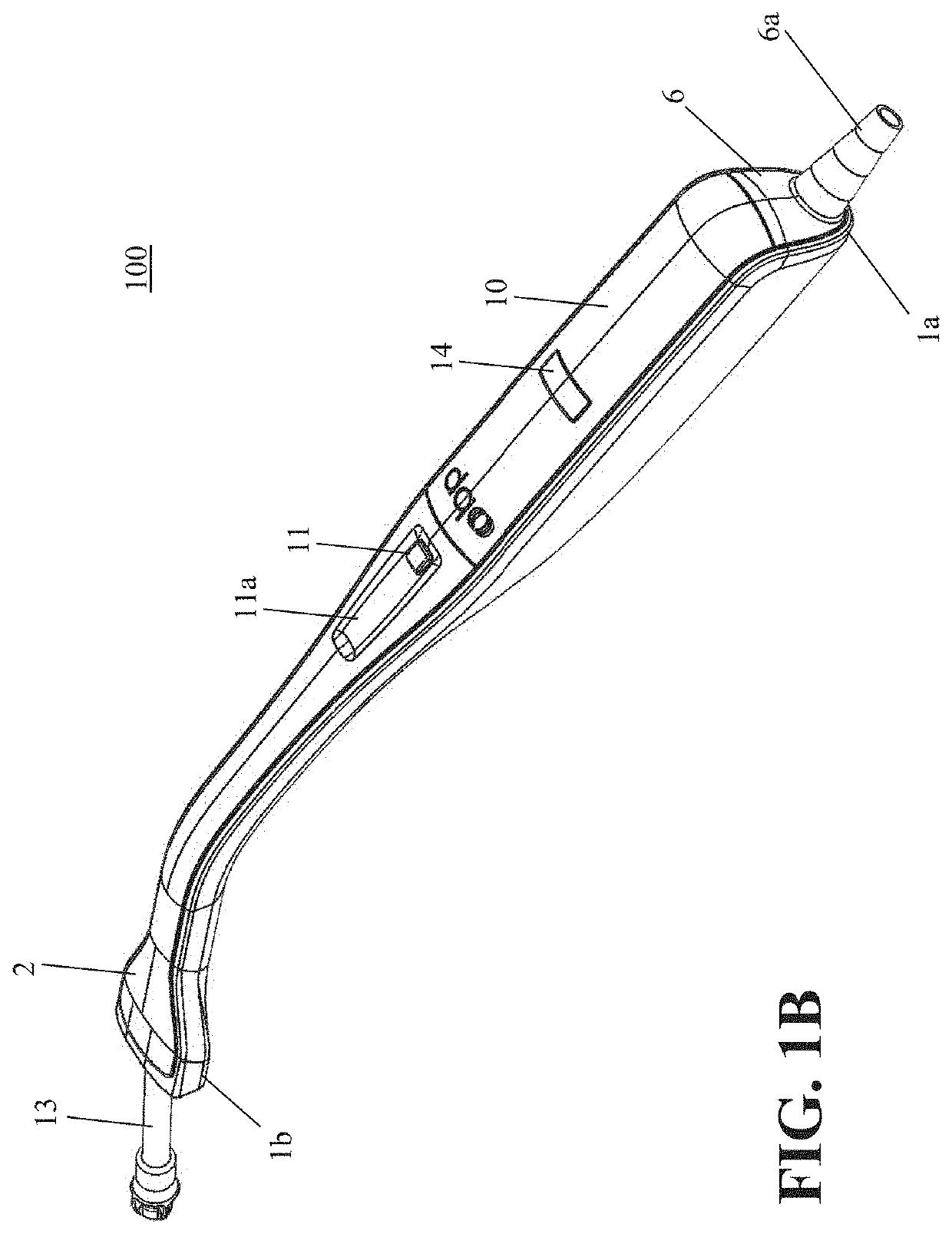
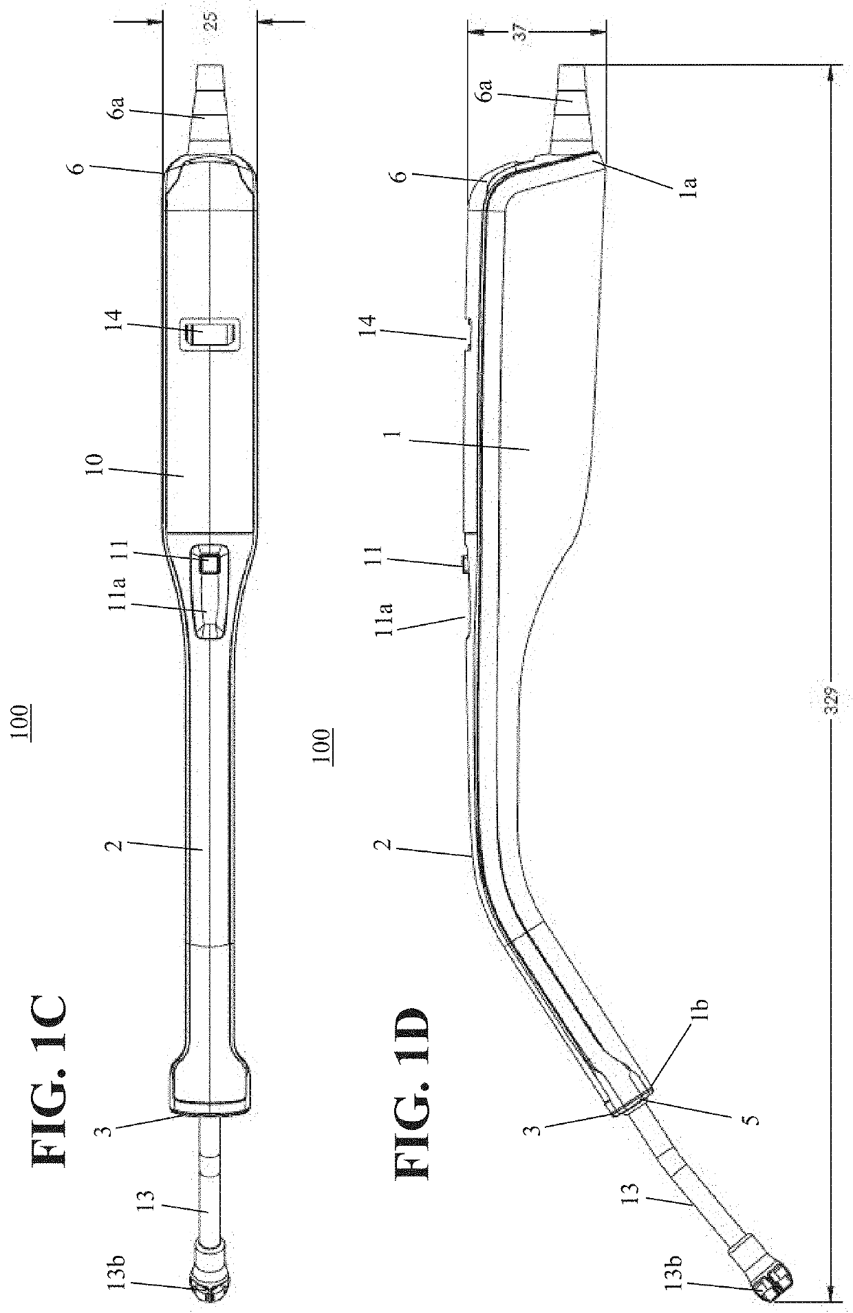
[0060]Drawings have been used herein to depict select exemplary embodiments. For the sake of clear illustration, many practical details are explained together in the description below. However, it should be appreciated that those details should not be used to limit the scope of any claims that issue in connection with this application. In some embodiments, certain details are not essential.

[0061]Moreover, for the sake of drawing simplification, some customary structures and elements in the drawings have been shown in a simplified way. Wherever possible, the same reference numbers are used in the drawings and the description to refer to the same or like parts.

[0062]Unless otherwise defined, all terms (including technical and scientific terms) used herein have the same meaning as commonly understood by one of ordinary skill in the art. It should be further understood that terms, such as those defined in commonly used dictionaries, should be interpreted as having a meaning that is cons...


PUM


Abstract

An illuminated medical device including an outer housing including a handle, an operative portion extending from the outer housing, and an illumination assembly comprising at least one direct light source oriented to emit light radially away from the operative portion of the medical device at least one reflector configured to reflect light from the at least one direct light source toward a target area external to the outer housing, wherein the at least one direct light source is positioned so as to maintain an air gap between the operative portion and the at least one direct light source.

Description

CROSS-REFERENCE TO RELATED APPLICATIONS[0001]This application is a continuation of U.S. patent application Ser. No. 16 / 815,556 filed on Mar. 11, 2020, which claims benefit of U.S. Provisional Application No. 62 / 968,805 filed on Jan. 31, 2020. The entire disclosures of these applications are incorporated herein by reference.FIELD OF THE INVENTION[0002]Embodiments described herein relate to a surgical instrument with a compact illumination assembly for improved lighting and heat dissipation features. The surgical instrument described in the illustrative embodiments herein is especially well suited for the removal of body fluids such as blood from a surgical wound and for simultaneously illuminating an area of the wound so that the same can be visualized by a surgeon.Introduction[0003]It is often necessary during the course of a surgical procedure for body fluids, such as blood, to be removed from the area of the surgical wound in order that the same may be visualized by the surgeon. T...

Claims


Application Information

Patent Timeline
Patent Type & Authority Applications(United States)
IPC IPC(8): A61B1/06A61M1/00
CPCA61B1/06A61B1/0684A61M1/0088A61M1/0031A61M2205/587A61M2205/6063A61M2205/8206A61M1/0039A61B90/30A61B1/128A61B1/0676A61B1/015A61M2205/3606A61M1/76A61M1/84A61B2090/309A61B2017/00734A61B1/0655A61M1/74A61B1/0625
Inventor SWIFT, JEFFREY RALPHCLARK, ADRIENNEDOMENICALI, PETER L.SWIFT, JASONTRAUB, MATTHEW
Owner OBP SURGICAL CORP
Why Eureka
Try Eureka